Users Guide Series 5 Digital Force Gages www.cooperinstruments.
This page intentionally blank
Table of Contents 1 OVERVIEW......................................................................................................................................1 2 POWER .............................................................................................................................................2 3 MECHANICAL SETUP ...................................................................................................................2 4 HOME SCREEN AND CONTROLS .................................
Thank you for purchasing a Cooper Series 5 digital force gauge, designed for tension and compression force testing applications from 0.12 lb to 500 lb (0.5 N to 2,500 N) full scale. The Series 5 is an essential component of a force testing system, typically also comprising a test stand, grips, and data collection software. With proper usage, we are confident that you will get many years of great service with this product.
3. The gauge should be serviced by a trained technician only. AC power must be disconnected and the gauge must be powered off before the housing is opened. 4. Always consider the characteristics of the sample being tested before initiating a test. A risk assessment should be carried out beforehand to ensure that all safety measures have been addressed and implemented. 5. Wear eye and face protection when testing, especially when testing brittle samples that have the potential to shatter under force.
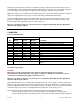
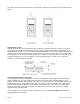
reassemble. Contact between the two halves is made by the spring pins and contact pads on the printed circuit boards. 3.2 Mounting to a plate Although the gauge may be used by hand, proper mounting is important if attached to a fixture or test stand. The round steel insert with a hole in the back of the housing is provided to withstand the load during a test. A mating dowel pin should be used (see illustration below).
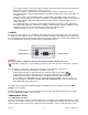
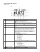
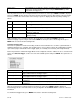
4 HOME SCREEN AND CONTROLS 4.1 Home Screen No. 1 Name Measurement direction 2 Peaks 3 Primary reading 4 Load bar 5 Units 6 Mode 7 Number of stored data points CF 183 Description - indicates a compression (push) direction - indicates a tension (pull) direction These indicators are used throughout the display and menu. The maximum measured compression and tension readings. These readings are reset by pressing ZERO or by powering the gauge off and on. The current displayed force reading.
Battery / AC adapter indicator Either the AC adapter icon, battery icon, or no icon will be shown, depending on power conditions. Refer to the Power section for details. 9 High / low limit indicators 10 Set points Correspond to the programmed set points. Indicator definitions are as follows: – the displayed value is greater than the upper force limit – the displayed value is between the limits – the displayed value is less than the lower force limit The programmed force limits.
For parameters requiring the input of a numerical value, use the UP and DOWN keys to increment or decrement the value. Press and hold either key to auto-increment at a gradually increasing rate. When the desired value has been reached, press ENTER to save the change and revert back to the sub-menu item, or press ESCAPE to revert back to the sub-menu item without saving. Press ESCAPE to revert one step back in the menu hierarchy until back into normal operating mode.
Trigger Force The minimum force required to start the averaging sequence. Toggle between compression and tension directions by pressing the DIRECTION key. Initial delay follows the trigger force. After the parameters have been configured and the menu has been exited, press MODE until AVG is displayed. Then press ZERO. Average mode is now armed, and the averaging sequence will commence when the trigger force has occurred.
Note: As long as external trigger has been enabled, it is still active even if the gauge is in Real Time mode. After the display freezes, any programmed set points will be active. However, if the gauge is in External Trigger mode, any programmed set points will be inactive. 6 DIGITAL FILTERS Digital filters are provided to help smooth out the readings in situations where there is mechanical interference in the work area or test sample.
If two set points have been enabled, they are displayed in the upper left corner of the display. If only one set point has been enabled, the word “OFF” will appear in place of the value. If no set points have been enabled, the upper left corner of the display will be blank.
Press ENTER to delete the value. To exit Delete mode, press DELETE again. Any number of readings may be individually deleted, however, all readings may also be cleared simultaneously. Refer to the Clear All Data section for details. 8.2 Statistics Statistical calculations are performed for the saved values. Calculations include number of readings, minimum, maximum, mean, and standard deviation. 8.3 Output Data Press ENTER to output data to an external device.
13 Click “Install”. 3. The next screen appears as follows: Click “Continue Anyway”. 4. After installation completes the following screen may appear in non-Windows 7 operating systems. Restart the computer before connecting a USB device. 5. After Windows as restarted, plug in the device. The following will occur: Windows 7 Operating Systems – When the USB device has been plugged into a USB port, the driver will automatically be found.
14 Select “No, not this time”, then click “Next”. 6. The next screen appears as follows: Select “Install the software automatically (Recommended)”, then click “Next”. 7. The next screen appears as follows: Click “Continue Anyway”. 15 8.
Click “Finish”. The USB device is now installed and ready to use. The COM port number assigned by Windows may be identified in Device Manager, or in the communication application being used, such as MESURgauge or HyperTerminal. 9.2 Serial / USB To set up RS-232 and USB communication, select Serial/USB Settings from the menu. The screen appears as follows: Select either RS-232 or USB input (output is always simultaneous through both the USB and RS-232 ports).
Select Enabled to activate automatic output. The number of outputs per second can be set to 1, 2, 5, 10, 25, 50, 125, or 250. The capabilities of the receiving device should be considered when selecting the data output rate. After the settings have been saved, revert to the home screen. An icon will appear in the lower left corner of the display, as follows: . This indicates that automatic data output has been armed.
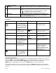
9.7 I/O Connector Pin Diagram (female) Pin No. 1 2 3 4 5 6 7 8 9 10 11 12 13 14 15 Description Signal Ground Tension Overload RS-232 Receive RS-232 Transmit +12V DC Analog Output Compression Overload Mitutoyo Clock Output Bit 2 Mitutoyo Data Output Bit 0 Mitutoyo Request Input Bit 3 “Under” Set Point “Over” Set Point “Within” Set Point External Trigger Mitutoyo Ready Output Bit 1 Input / Output --Output Input Output Output Output Output Output Output Input Output Output Output Input Output 9.
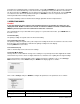
PC CLR Z Peak Compression mode for primary reading Clear peaks Zero display and perform the CLR function Filters FLTCn Digital filter for displayed readings FLTPn Digital filter for current readings n= 0-10, filter = 2n, ex: n=0= no filter, n=10=1024 samples averaged Memory & Statistics MEM Transmit all stored readings STA Transmit statistics Set Points SPHD Disable high set point SPLD Disable low set point SPHn High set point. n=value (+ for compression, - for tension) SPLn Low set point.
RS Read serial number Other Commands AOFFn Auto-shutoff. n=0-30 minutes. 0=auto shutoff disabled SAVE Save current settings in nonvolatile memory LIST List current settings and status Following is an example LIST output: V1.00;LBF;CUR;FLTC8;FLTP1;AOUT00;AOFF5;FULL;MIT;POL;B0 All fields are separated by “;”. The first field shows the firmware version, the last field shows the remaining battery power (B0=full charge, B3=minimum power).
Selecting “CANCEL” will revert back to the Calibration setup. Selecting “EXIT W/O SAVING” will return to the menu without saving changes. 4. After the number of calibration points has been entered, press ENTER. The display will appear as follows: 5. Place the force gauge horizontally on a level surface free from vibration, then press ZERO. The gauge will calculate offsets, and the display will appear as follows: 5 6.
Optionally exercise the load cell shaft several times (at full scale, if possible), then press ENTER. 8. The display will appear as follows: Apply a weight equal to the full scale of the instrument, then press ENTER. 9. After displaying “PLEASE WAIT…” the display will appear as follows: 22 Remove the load applied in Step 8, leave the fixtures in place, then press ZERO. 10. The display will appear as follows: Use the UP and DOWN keys to adjust the load value as required.
Reverse the orientation of the load cell shaft by rotating the gauge 180 degrees. Press DIRECTION to invert the display. Then attach weight fixtures. The following screens will step through the same procedure as with the compression direction. Proceed in the same manner. 13. At the completion of the tension calibration, the display will appear as follows: To save the calibration information, select “SAVE & EXIT”. To exit without saving the data select “EXIT W/O SAVING”. 14.
11.1 Calibration Password Select Calibration from the sub-menu. The display will appear as follows: To set the password, select Enabled, then Set Password. Use the UP and DOWN keys to increment and decrement the value, from 0 to 9999. When the desired value has been selected, press ENTER, then ESC to exit the sub-menu. 11.2 Menu Key Password If enabled, every time the MENU key is selected, a password must be provided. Select Menu Key from the submenu. Follow the same procedure as described in section 10.1.
12 OTHER SETTINGS 12.1 Automatic Shutoff The gauge may be configured to automatically power off following a period of inactivity. Inactivity is defined as the absence of any key presses or load changes of 100 counts or less. To access these settings, select Automatic Shutoff from the menu. The display will appear as follows: Select Disabled to disable automatic shutoff. Select Enabled to enable it. The length of time of inactivity is programmed in minutes via the Set Minutes parameter.
12.5 Initial settings This section is used to configure the initial settings upon powering on the gauge. The initial units of measurement and the primary reading measurement mode may be configured. To access these settings, select Initial Settings from the menu. The screen will appear as follows: The default values are LBF and Real Time. 27 12.
Parameter Set points Upper Lower Filters Current Displayed Average mode Initial Delay Trigger Force Averaging Time External Trigger DATA Key RS-232/USB Mitutoyo Memory Storage Backlight Minutes (applies to Auto) Serial/USB RS-232 Selected USB Selected Baud Rate Data Format Auto Output Outputs per sec Mitutoyo BCD Automatic Shutoff Minutes (if enabled) Beeps Keys Alerts Set Points LCD Contrast Initial Settings Units Mode Passwords Setting Disabled (defaults to 80% of full scale when enabled) Disabled (defau
13.