
Owner's manual


CF 189 9 Rev. E; Dec. 12, 2011
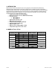
7.0 CONNECTION PLAN
Pin assignment at Sensor.
Presentation: Top view
Model Binder Series 423/723/425
Item number: 09-0132-90-12
Color code according to DIN 47100
Pin Color Description Value
A White Supply voltage
V
CC
11V…28V
B Brown Ground GND
C Green Analog Out 0V…10V
D Yellow Analog GND
E Grey PWM / Frequency /
4-20mA
F Pink Angle Ch A / 0V…5V
G Blue Angle Ch I 0V…5V
H Red Angle Ch B 0V…5V
I Black -
K Violet For internal use only Do not connect
L Grey-Pink For internal use only Do not connect
M Red-Blue Digital GND
Connection example
8.0 OPERATING INSTRUCTIONS
8.1 Field of Application
The torque sensor is intended for the use in industrial applications. (e.g. test bench).
8.2 Scope of Delivery
The torque sensor set consists of the sensor itself (signal pick-up and signal processing integrated into
sensor housing), one connecting cable with a soldered plug, key stones and the instruction manual.