
Manual

CF59 3 Rev.ISeptember2013
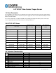
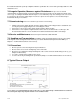
Dimensions
Nominal Torque Capacity
[Nm]
A B C D E F G H
K
L M N P S
LXT 970
¼ inch
2.5 - 5.0 - 7.5 - 17.5 95.5 70 9.5 - 40 16
8 5 12 - 43.9 15 37 1.5
3/8 inch
75
107 70 13 - 50 24 8 5 18 - 43.9 18 47 1.5
½ inch 175-250 123.5 70 18.5 - 50 35 8 5 24 - 43.9 18 47 1.5
¾ inch 500 146 87 29.6 - 60 29.6 10.5 2 33.5 - 61.4 19 57 1.5
LXT 971
Ø 9 mm
2.5 - 5.0 - 7.5 - 17.5
125 70 27.5 9 40 - 8 5 - 23 43.9 15 37 1.5
Ø 14 mm 75 139 70 34.5 14 50 - 8 5 - 30 43.9 18 47 1.5
Ø 19 mm 175-250 179 70 54.5 19 50 - 8 5 - 50 43.9 18 47 1.5
Ø 25 mm 500 220 87 66.6 25 60 - 10.5 2 - - 61.4 19 57 1.5
The second Key Way (only for LXT
971 500) in mirrored position (180°)
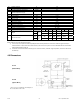
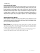
5.0 Connection Plan
Pin Color Description Value
1 White Supply Voltage V
cc
9V – 12V
2 Brown Signal Output analog
3 Black Ground GND
4 Blue Not Used
5 Grey Reference Voltage V
re
f
2.5v
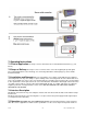
TheoutputV
ref
isaconstant2.5Vandrepresentsthevirtualzeropointfor
direct+/‐torquemeasurement(Seebe low “ Sensor cableconnection”sectionB).
At the user side one plug with shielding termination (360°) should be used. If not possible the
shielding should accompany the signal as far as it could!
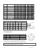
Dimensions Keyway [mm] Keystones
Shaft
Diameter
Width Depth Length Height Length
A
mount
Ø 9 mm 3 1.8 18.5 3 18 1
Ø 14 mm 5 3 25.5 5 25 1
Ø 19 mm 6 3.5 45.5 6 45 1
Ø 25 mm 8 4 50.5 8 50 2