ELF 4200 Load and Force System Single Handle, Multi-Handle, and Hi-Speed Systems Version 3.4x USER’S GUIDE www.cooperinstruments.
CONTENTS 1.0 INTRODUCTION ....................................................................................................................1 2.0 QUICK START .......................................................................................................................1 3.0 INSTALLATION .....................................................................................................................5 3.1 Software Installation .....................................................................
11.0 GLOSSARY........................................................................................................................48 WARRANTY REPAIR POLICY ..................................................................................................54 CF10 iii 6/24/08 Rev.
1.0 INTRODUCTION This manual describes how to use FlexiForce’s Economical Load & Force (ELF) system, Multi-Handle ELF and HiSpeed ELF. These systems are ideal for designers, researchers, or anyone who needs to measure forces without disturbing the dynamics of their tests. The FlexiForce sensors can be used to measure both static and dynamic forces (up to 1000 lbf), and are thin enough to enable non-intrusive measurement.
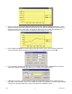
4. Apply the test force to the sensing area of the sensors (refer to the “Sensor Loading Considerations” section and ensure that the sensors are conditioned before use). The force data will be displayed in the window in the default mode, which is as a "Strip Chart". This shows the data in the form of a chart, with elapsed time (in seconds) on the X-axis, and the selected units (default is "percentage") on the Y-axis. 5.
8. Select the desired recording parameters under Record -> Settings. The default Recording Type is "Infinite (8 Hz, user stops)", but you are given the option to stop the recording after a specific number of frames. You may also set recording frequency, trigger and threshold, as well as frames to record, in this dialog box. 9. Click Record -> Start (or the Start Recording icon on the Toolbar). The system will begin recording data.
10. Select File -> Save As to save the movie. Under File Name, enter the desired file name (e.g.: "test1.flf") and select the destination (path) where you want to save your recording. Recordings must be saved as ELF Movie Files (with the extension *.flf). 11. Click on one of the Playback Control icons on the toolbar at the top of the Movie window to play the movie forward or backward, move one frame forward or backward, move to the first or last frame, or stop the movie. 12.
Windows clipboard, and will be available to be pasted as a graphic (bitmap) into other Windows applications. 13. Select File -> Save ASCII to save the movie data as a text file. ASCII files must be saved with the extension *.csv. This data can then be viewed by importing it into a spreadsheet program, such as MS Excel, or by opening the text file in a word processing program, such as MS Word. You have now completed the Quick Start section, and should be acquainted with your ELF software.
The following displays the ELF system with USB Handles. Note: Our previous systems shipped with Serial handles. It is not recommended to use both the Serial ELF and USB ELF handles simultaneously. Note: For the Hi-speed Multi-Handle ELF software using Windows 2000/XP/Vista, you will need a PCI board and we would recommend that you use no more than 4 handles. ELF COMPONENT IDENTIFICATION The following lists all the components that come with the ELF system. CF10 6 6/24/08 Rev.
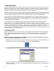
3.1 Software Installation Before installing the ELF software, close all other applications. To install the software, place the CD-ROOM in your CD-ROM drive. If the autorun.exe does not start automatically, click on Start at the bottom left of the screen, and click on the Run menu item. If you put the disk in the D: CD-ROM drive, type “d:setup” in the Command Line field of the Run dialog box, then click .
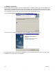
Next, the installation program will copy the necessary files to your computer. The default location is C:\Tekscan\Elf, however, you can change this location by clicking the Change button and designating a destination of your choice on your computer’s hard drive. At this point, your computer has the necessary information to proceed with the installation of your ELF program. Click the Install button to begin installing the program on your computer.
The next screen that will appear offers you the options to place a shortcut icon on your desktop and view the README file. If you elect to view the README file, it will open in a MS Notepad window, where you can read about new and updated information regarding the latest release of the ELF software. CF10 9 6/24/08 Rev.
When the installation is completed, you will need to restart your system. Click the Finish button, and your system will be automatically rebooted. You cannot start the ELF software without first restarting. The ELF splash screen will be shown (below). This indicates the ELF software is successfully loaded on your machine. The installation process is now complete.
Multi-Handle system with handles connected to the USB hub CF10 11 6/24/08 Rev.
CF10 12 6/24/08 Rev.
4.0 OVERVIEW This section outlines the Various Hardware and Software components that ship with your system. 4.1 Sensors The sensor is an ultra-thin and flexible printed circuit. Sensors are available in three full-scale force ranges: Low (25 lbf ), Medium (150 lbf ), and High (1000 lbf ). The "active sensing area" is a 0.375. diameter circle at the end of the sensor. The sensors are constructed of two layers of substrate, such as a polyester film.
Note: Familiarity with MS Windows is assumed, so menu items that have the same function in standard Windows applications are not described in this manual. 4.3.2 Main Window When you initiate the ELF software program, the Main Window is displayed on your computer screen. The Main Window consists of the Menu Bar, Tool Bar, and Main Status Bar, and may contain one or more Real-time or Movie Windows. The window that is selected is considered the active window.
Toolbar: provides some of the same options as the Menu Bar, but with icons replacing drop-down menus. It is located directly below the Menu Bar, at the top of the Main Window. Note that not all items in the Menu Bar have a corresponding icon on the Toolbar. Two icons on the Toolbar do not have corresponding pull-down menus. They are the Increase Decimal and Decrease Decimal buttons. When sensors have been calibrated, units of force will be shown.
• • • • • Stop: Stops playback. Next Frame: Plays the recording forward one frame each time it is clicked. Play Forward: Plays the recording forward. Last Frame: Positions the recording at the end (last frame) Movie Window Status Bar is located at the bottom of the Movie Window, and displays the "Frame count" (the current frame number vs. the total number in the movie). Directly above this status bar is a "scroll bar", which can be used to move to any point (frame) in the movie. 4.4 THE MAIN MENU 4.4.
New: opens a new Real-time Window, in addition to any other Real-time or Movie windows that are currently open. The new Real-time Window becomes the active window when it is opened. If more than one Real-time Window is open, the force data will be displayed in all windows, in unison. If the sensor has already been calibrated, this calibration will also apply to the new Real-time Window. Before your Real-time Window opens, the Select Button dialog box is displayed.
Close: causes the currently active Real-time or Movie Window to close. If a movie has been recorded, but not saved, the software gives the option of saving the movie file. Save As: will save the current movie with the specific file name and location of your choice. ELF movie files must have the extension *.flf. Your system may limit filenames to eight characters. This menu item can be used to save a movie file under more than one filename.
used (refer to the Settings menu item). Seconds 0 0.125 0.25 0.375 Sensor 1 7.894737 44.73684 97.36842 134.2105 Sensor 2 5.263158 15.78947 92.10526 171.0526 Sensor 3 5.263158 5.263158 15.78947 73.68421 4.4.3 Edit Menu Edit Menu (same when focus is on either a Real-time or Movie Window): Copy: saves the current Real-time or Movie frame to the MS Windows clipboard. This data is saved in the clipboard as a graphic (bitmap) image of the current window.
Column: displays each COM port individually, with force value displayed on the Y-Axis. Each column is colorcoded to indicate the individual COM ports. As time elapses, the columns indicate changes in force. Number: displays each COM port as numerical values. Each numerical value is color coded to indicate the individual COM ports. As time elapses, the numbers change to indicate changes in force. Toolbar: This item is used to display or hide the Movie and Main Toolbars.
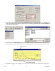
Properties: opens the Properties dialog box (shown following), which allows you to change how the data is displayed on the screen. Any changes made here will only affect the currently active Real-time or Movie Window. The Properties dialog box will also appear whenever you click the right mouse button over a Real-time or Movie Window. Under View, you can select whether to display the force data as a Strip Chart, Column, or Number.
Stop: will cause the software to stop recording the active Real-time Window, even if the correct number of movie frames (as selected in "Settings") have not yet been recorded. Settings: brings up the Recording Parameters dialog box, which allows you to change the current recording parameters. Under .Recording Type,. there are three possibilities that may be selected.
When Fast Recording, is selected, the "Frames to Record" may be entered, and the Recording Frequency (Hz) may be selected to the right. In "Fast Recording" applications, recordings can be obtained at frequencies of 10, 25, 30, 50, 60, 100, and 200 Hz. The Duration is listed below the Recording Type; it will either say "Until Stop" if Infinite is selected, or the approximate duration (in seconds) the recording will take to complete if Frame Count is specified.
The Threshold may be set for each individual COM port, so that each sensor has a different threshold. This may be used in combination with the Trigger Force value to begin recording when force is exerted on a specific sensor. Note: If no calibration has been performed, the only available units will be shown as a Percentage. If a calibration has been performed, you may select from a number of force units.
4.4.6 Tools Menu Tools Menu when focus is on a Real-time Window: Tools Menu when focus is on a Movie Window: Calibrate: Opens the ELF Calibration dialog box, which enables you to calibrate the sensor and adjust the system sensitivity. Refer to the Calibration section for the complete calibration procedure and a thorough description of the process.
If you wish to recalibrate the sensor during the same testing session, you may either select File -> New to get a new Real-time Window, or select Tools -> Uncalibrate to reset the calibration of the current window. The current calibration will be saved between sessions, unless Uncalibrate is selected. A dialog prompt will open asking if you are sure you want to uncalibrate.
Load Calibration: allows you to use the calibration data from a previously-saved file for your current Real-time Window. When this item is selected, an Open dialog box appears, and the calibration file can be located and opened. Only ELF calibration files (extension *.clb) can be loaded. The Sensitivity setting that was saved with the calibration file will also be loaded. Save Calibration: allows you to save your current calibration as a file for future use.
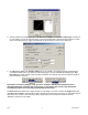
Change Unit: This feature allows you to quickly change the force units displayed in all windows. To use this feature, however, you must have performed a calibration. Otherwise, all force will be displayed as "raw values". Change Sensitivity: This feature opens the Change Sensitivity Dialog box (below). You may adjust the sensitivity for each sensor/COM port. Use the drop down Select Buttons field to select the COM port. Then drag the slider up and down until you are satisfied.
raw before the calibration scale factor is applied. Zeroing Preload is recommended only for single point calibration and may increase error when using a multi-point calibration. 4.4.7 Window Menu Window Menu (same when focus is on either a Real-time or Movie Window): New Window: opens a copy of the currently active Real-time or Movie Window. A number will be added to the title of the new window, to show that it is a copy. For example, if Movie1.
4.4.9 Help Menu Help Menu (same when focus is on either a Real-time or Movie Window): Help Topics: opens the help file associated with the Multi-Channel ELF software. About ELF: opens the About ELF dialog box, which displays the software and hardware (device) version numbers for your ELF system, and gives you information on how to contact Tekscan (shown below). 5.
load path goes through this area. The puck must not touch any of the edges of the sensing area, or these edges may support some of the load and give an erroneous reading. The FlexiForce sensor reads forces that are perpendicular to the sensor plane. Applications that impart "shear" forces could reduce the life of the sensor. If the application will place a "shear" force on the sensor, it should be protected by covering it with a more resilient material.
• Piece Wise Linear Calibration: This calibration connects each calibration point directly and interpolates between the values. NOTE: if you have a Multi-Handle ELF system, all handles must use the same type of calibration. Linear and Best Fit cannot be mixed and matched. The "Sensitivity" (or "Adjustable Gain") is also adjusted in the ELF Calibration dialog box. This adjustment sets the data output range from the computer (0 to 100%) to the actual force range output from the system handle.
6.1 CALIBRATION GUIDELINES The following guidelines should be considered when calibrating a sensor: • Apply a calibration load that approximates the load to be applied during system use, using dead weights or a testing device (such as an MTS or Instron). If you intend to use a "puck" during testing, also use it when calibrating the sensor. See Sensor Loading Considerations for more information on using a puck. • Avoid loading the sensor to near saturation when calibrating.
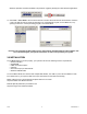
4. Click on Tools -> Calibrate. This brings up the Calibration dialog box. 5. Select Best Fit Linear calibration or Piece Wise Linear calibration. 6. Select the Port/Device you wish to calibrate first. If you have the Multi-Handle ELF system, all Port/Devices must be calibrated before you may select Finish. CF10 34 6/24/08 Rev.
7. Select the appropriate Force unit from the drop-down box (grams, kilograms, Newtons, pounds). 8. Load the sensor with a known force. The key to an accurate calibration is applying a stable load. Enter the known load in the Cal Force field. If the applied force is not stable, an error message will appear which requires you to either accept or cancel the current calibration. It is recommended that you stabilize the force; otherwise, your calibration may be inaccurate.
9. Click Add Point. A point will appear in the Multipoint Calibration box (shown above). 10. Repeat the steps with as many known loads as you wish. 11. If you wish to discard any points, click to highlight them in the Force/Raw column. Then select Remove Point. 12. If you have the Multi-Handle ELF system, continue selecting Port/Devices and adding as many known loads as you wish, until at least one calibration point has been added for each sensor. 13.
14. If you wish to save the calibration file for future use, select Tools -> Save Calibration, and enter the desired destination and file name in the Save As dialog box. Calibration files must be saved with the *.clb file extension. Sensitivity settings are saved with calibration files. 15. If you wish to recalibrate the sensor during the same testing session, you may either select File -> New to get a new Real-time Window, or select Tools -> Uncalibrate to reset the calibration of the current window.
calibration will be saved between sessions unless Uncalibrate is selected. 7.0 SENSOR PERFORMANCE CHARACTERISTICS There are a number of characteristics of sensors, which can affect your results. This section contains a description of each of these conditions, and recommendations on how to lessen their effects. 7.1 REPEATABILITY Repeatability is the ability of the sensor to respond in the same way to a repeatedly applied force.
flanged joint will have a shorter life than a sensor installed in the same joint once and used to monitor loads over a prolonged period. After each installation, visually inspect your sensors for physical damage. It is also important to keep the sensing area of the sensor clean. Any deposits on this area will create uneven loading, and will cause saturation to occur at lower applied forces. 8.
8.2.1 Power Hub: Transmitter: AC Adapter: USB powered. USB voltage range is 4.75 V. – 5.25 V. 200 mA max. Voltage range 4 VDC min. – 7VDC max 180 mA max. Input: 100 VAC – 240 VAC; 50 Hz. – 60 Hz.; 0.6 A. Output: 5 VDC; 2.6 A. 8.2.2 Environmental Conditions Temperature: °F (°C) Humidity: % Pressure: psi (kPa) 14 to 131 (-10 to 55) Prolonged use at higher end of temperature range should be avoided. 0-90 (non condensing) 1.7 to 14.7 (11.6 to 101.3) (sea level to 50,000 ft.) 8.
2. Remove the back transmitter plate to reveal the electronics inside. 3. Insert 3 AAA batteries into the exposed battery compartment as shown. 4. Place the top plate over the electronics. Insert the screw into the back plate. Tighten the screw, being careful not to strip the screw. 8.4 TROUBLESHOOTING If you are having problems running the Wireless ELF system, try turning off your wireless internet connection. The Wireless ELF system may be experiencing interference with the wireless internet signal.
CF10 42 6/24/08 Rev.
CF10 43 6/24/08 Rev.
CF10 44 6/24/08 Rev.
CF10 45 6/24/08 Rev.
CF10 46 6/24/08 Rev.
CF10 47 6/24/08 Rev.
11.0 GLOSSARY A About Elf (Help Menu): The "About Elf" command displays a dialog window with information about the software version, as well as contact information for Tekscan. Adjustable Gain: See "Sensitivity". Arrange Icons (Window Menu): The "Arrange Icons" arranges the icons for minimized windows at the bottom of the main window. B Best Fit Linear Calibration: This calibration creates a best-fit curve through two known force values.
E ELF Hardware: The ELF hardware consists of the sensor handle(s), ELF software, and the SSB-F (Single Sensing Button - Flexiforce) sensors. ELF Software: The ELF software is a 32-bit application that is compatible with Microsoft (MS) Windows 95/98 and NT. The software allows you to view a graphical representation of the force on the sensor in real time, record this information as a ‘movie’, and review and analyze it later.
Load Calibration (Tools Menu): The "Load Calibration" command allows you to use the calibration data from a previously-saved file for your current Real-time window. When this item is selected, an ‘Open’ dialog box appears, and the calibration file can be located and opened. Only ELF calibration files (extension *.clb) can be loaded. The Sensitivity setting that was saved with the calibration file will also be loaded.
how the data is displayed on the screen. Any changes made to the Properties will only affect the currently active Real-time or Movie window. The Properties dialog box will also appear whenever you click the right mouse button over a Real-Time or Movie Window. You can select a display option ("Strip Chart", "Column" or "Number"), and also change the "Scale Max", "Scale Min", and "Units". R Real-Time Window: A Real-time Window displays the load applied to the sensor as it is happening (in Real-time).
over a prolonged period. After each installation, visually inspect your sensors for physical damage. It is also important to keep the sensing area of the sensor clean. Any deposits on this area will create uneven loading, and will cause saturation to occur at lower applied forces. Sensor Temperature Sensitivity: The operating range for FlexiForce sensors is from 15°F (-9°C) to 140°F (60°C). FlexiForce sensor output may vary up to 0.2% per degree F (approx. 0.36% per degree C).
Toolbar (View Menu): The "Tool Bar" option is used to display or hide the Movie and Main Tool Bars. These tool bars can be toggled by clicking this menu item on and off. If a Real-time window is active, this menu item affects the Main Tool Bar. If a Movie window is active, this menu item affects the Movie Tool Bar. Trigger Force: See "Triggering". Triggering: Refers to the Recording Parameters dialog box. This dialog box allows you to .trigger. the start of a recording based on a force value.
WARRANTY REPAIR POLICY Limited Warranty on Products Any Cooper Instruments product which, under normal operating conditions, proves defective in material or in workmanship within one year of the date of shipment by Cooper will be repaired or replaced free of charge provided that a return material authorization is obtained from Cooper and the defective product is sent, transportation charges prepaid, with notice of the defect, and it is established that the product has been properly installed, maintained, an