Dynamic Transducers and Systems 21592 Marilla St. • Chatsworth, CA 91311 • Phone 818-700-7818 www.dytran.com • e-mail: info@dytran.
Contents 1 Device Features ................................................................................................................................................. 3 2 VibraScout™ Software Features ........................................................................................................................ 3 3 Acronyms used in this manual ..........................................................................................................................
The Dytran 7543A USB Digital Tri‐axial Accelerometer combines a 3‐Axis MEMS accelerometer with a microcontroller to create an intelligent sensor. 1 Device Features ‐System components: USB 7543 Accelerometer 6330A 4‐pin to USB cable VibraScout™ Software and VibraScoutTMPP on CD ‐The 7543A is powered by a PC’s USB bus. ‐Temperature sensor. ‐Real‐time acquisition and USB transfer of acceleration (including Static Inclination) and temperature data.
‐ ‐Fast Fourier Transform Plots of all orthogonal channels. ‐ API available as .
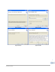
Figure 1: Step 1 Figure 2: Step 2 Figure 3: Step 3 Figure 4: Step 4 5 REV B 10/18/12, ECN 8972
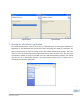
Figure 5: Step 5 Figure 6: Step 6 7 Starting the VibraScout™ application The 7543A Accelerometer must be connected to a USB port prior to starting the VibraScout™ application or the application will not function. After connecting the 7543A to a USB port, the device enumerates as an external storage device with 5 KB of available file storage. The drive space can store up to three VibraScout™ parameter files or other customer files.
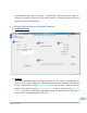
Run VibraScout™ (All Programs ‐> Dytran ‐> VibraScout™). After detecting the 7543A, the software will perform a self‐test to verify that the device is functioning properly and then display the VibraScout™ application. 8 GUI layout & Description of Software Features 1. Configuration Screen Figure 8: Configuration Window 2. File Menu All GUI fields (bandwidth selection, FFT plot selections, etc) are stored in a configuration file. Fields are read from the default file VibraScoutConfig.
Current plot data can be exported to a selected tab‐delimited file for convenient importing in a spreadsheet or other application such as the VibraScout Post Processor. This feature provides an alternative to the data log file by allowing the user to export data after acquisition. 3. Device Info Model # and Serial # are stored in the device EEPROM and read when the VibraScout™ application is launched. Device memory is also available to store user information.
The Relative mode must be selected on the Acquisition screen so offsets will be subtracted from the respective data during acquisition. To reset the 7543A to factory defaults, simply select the Abs radio button in the Acquisition screen. 7.
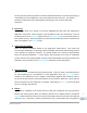
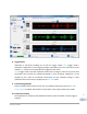
Figure 9: Acquisition Window 8. Trigger Modes Acquisition is started by enabling one of the two trigger modes. Auto Trigger mode is amplitude independent so that triggering begins immediately and runs continuously when enabled. i.e. similar to an oscilloscope auto triggered scroll mode. Smart Trigger mode starts data acquisition when the first change in value on any of the three acceleration axes exceeds the specified threshold in Units of Gpk‐pk. Acquisition is to be stopped by user.
. Data Integrity Indicator The Data Integrity box indicates one of three conditions: OK, Overflow, or Checksum Failure. An overflow condition occurs when system resources are inadequate to sustain data processing at the selected bandwidth. This might be due to CPU speed, insufficient free memory or cpu/memory ‐ intensive processes running concurrently with the VibraScout™ application. An overflow indicates a loss of some data samples. The condition can usually be eliminated by selecting a lower bandwidth.
FFT data can be exported to a delimited file by clicking the Export button on the FFT form.
Figure 12: FFT Log format 17. Plot Features Press the Stop button to halt chart scrolling. Left‐clicking, dragging, and releasing the cursor will zoom the plots in a desired location. Vertical and horizontal scroll bars are displayed when data exceed the vertical and horizontal ranges respectively.
Right‐clicking on plots (both time‐domain and FFT) will display a context menu with available features ‐ zooming, saving, printing, etc. as shown on the menu below. Figure 15: Point Value Display Select Figure 16: Point Value Displayed 9 Custom Applications An API is available for customers who would like to build custom applications for the 7543A. The API provides support for any .NET‐compatible client application ‐ e.g. LabView, C#, etc. Please contact Dytran at sales@dytran.com or 818‐700‐7818.
Reproduce interpolated oversampled data to provide better resolution of vibration signals Multiple file types to export to including: ASCII, time history.JPG files, TDMS binary files of time history data readable in Microsoft Excel, PSD and FFT plots in Joint Photographic file format. Display of recorded average temperature 11 Minimum System Requirements Personal Computer running Windows XP/Vista/7 x86 or Windows XP/Vista/7 x64 with at least 2GB RAM or higher.
Figure 17: Installation File Figure 18: Welcome Screen and Software Version Figure 19: Installation Directories 16 Figure 20: Products to be installed REV B 10/18/12, ECN 8972 Figure 21: Installation Progress
Figure 22: Installation Completed 13 Starting the VibraScout™ PP application After System reboot, from the Desktop, double click the VibraScout™ PP icon. 14 Software Operation I. Software Revision Press F1 key on the keyboard or navigate to Help>About to display the current version and date of the Software. See Figure 23 for location on window. Press anywhere on the window to hide it.
II. Select Data Tab 1. Select File‐ to select the data file recorded using the VibraScout™ software. A prompt window will pop up asking for data file to be selected. Navigate to folder where file exists and double click on data file. Note: all exported files will be saved to the same directory as the original data file directory. 2. 3. 4. 5. 6. Model Number‐ Once file is opened, Model number of the transducer will be displayed in this field.
13. Re‐sampling frequency‐ There are 7 different settings for re‐sampling recorded data: 10KHz, 20KHz, 30KHz, 40KHz, 50KHz, 70KHz, and 100KHz. It is recommended to use the lowest available sampling rate for longer duration of recordings to prevent system from running out of memory during processing. Window‐ is the PSD window and Hanning window is the most commonly used to perform the PSD calculations. Units‐ there are 2 settings for this field. Most commonly used for PSD is EU^2/Hz. 14. Min.
Figure 25: Select specific window for Re‐sampling Figure 26: Re‐sampling and output file parameters 20 REV B 10/18/12, ECN 8972
15 Software License, Restrictions, and Disclaimer LICENSE: The Dytran Instruments, Inc. (Dytran) VibraScout™ software application (the Software) available for download via the Dytran website, via email, or made available on portable storage devices shipped with Dytran products is a free license for Dytran customers to use with Dytran products. Dytran encourages you to know the possible risks involved in the download and use of Software from the Internet.
Model Number DOC NO PS7543A PERFORMANCE SPECIFICATION 7543A USB TRIAXIAL ACCELEROMETER REV C, ECN 9403 This family also includes: Model Input Range (g) Frequency response (Hz) Non-Linearity (%F.S) Noise Differential (μg/√Hz) Max.Shock • USB/MEMS TECHNOLOGY • EMBEDDED MICROCONTROLLER • HERMETICALLY SEALED • DC RESPONSE • POST PROCESSOR INCLUDED TO EXTEND FREQUENCY RESPONSE Refer to the performance specifications of the products in this family for detailed description.