DPG 100 DIGITAL PRESSURE GAGE USER’S GUIDE http://www.cooperinstruments.
CONTENTS CHAPTER 1 1.1 1.2 GETTING STARTED...........................................................................................1 Quick Start Guide ...................................................................................................................... 1 About This Manual ................................................................................................................... 1 CHAPTER 2 INTRODUCTION ...........................................................................
CHAPTER 6 FIELD SELECTABLE FEATURES ...................................................................15 Introduction ...............................................................................................................................15 6.2 Setup Menu Operation ............................................................................................................ 15 6.3 Low Limit Setpoint ("L-LO") Menu Item ................................................................................
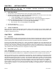
CHAPTER 1 GETTING STARTED IMPORTANT! IT IS RECOMMENDED THAT YOU READ THIS DOCUMENT THOROUGHLY BEFORE APPLYING POWER TO THIS UNIT. THIS DOCUMENT CONTAINS INFORMATION ON WIRING, CALIBRATION, AND USE OF FEATURES. 1.1 Quick Start Guide 1. The instrument comes calibrated from the factory and needs no further calibration. 2. For battery powered instruments, install one or two alkaline batteries by removing the rear center screw and then the front faceplate. See "Battery" in Section 3.3.
2.2.2 Low Battery Indicator On the left side of the display, just above the minus sign, is the low battery indicator (in the shape of an arrow). When the battery voltage is less than 5 volts, the display will be blanked and the low battery indicator will illuminate to indicate that the batteries should be replaced. The low battery indicator can be seen when the instrument is turned on and all segments of the display are momentarily lighted.
2.
2.
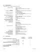
2.6 Specifications These specifications are subject to change without notice.
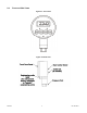
CHAPTER 3 3.1 SET UP Installation When installing the instrument into a process connection, make sure all backpressure is relieved from the system. Make sure that you use the proper fitting to mate with the instrument. To connect to the pressure fitting, use: • 1/4-18 NPT for ranges below 500 PSI (3/4" hex wrench) • 9/16-18 UNF-2B (straight thread) for ranges 500 PSI and above (7/ 8" hex wrench). An O-ring is needed to seal the connection. Failure to use the correct fitting will result in leaks.
3.3 Power Supply Options 3.3.1 Battery Two nine-volt alkaline batteries (NEDA 1604) are recommended operation. This is a common type of battery that is available at many stores. With two alkaline batteries, the instrument can operate continuously on for approximately 3 weeks. Carbon-zinc batteries (sometimes labeled as "general purpose" or "heavy duty") should not be used. Please note that the temperature specifications of the batteries you purchase may not be the same as those of the instrument.
3.6 Restoring the Calibrated Zero To restore the zero, first press and hold the [Clear] button, and while holding ... ...press the [Zero] button. Hold both buttons until the display shows "-PO-", then release. The "calibrated zero" is the zero value of the instrument at the time it was last calibrated. Restoring the calibrated zero can be used to "undo" an inadvertent press of the [Zero] button. 3.
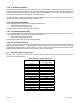
4.2 Required Pressures In order to re-calibrate the instrument, you must have a precision pressure standard that can produce the zeroscale, half-scale and full-scale pressures for the instrument's range. Examine the table below to determine the three pressures needed to calibrate your instrument. For example, if your instrument has a range of 100 PSIG, your pressure standard must be able to accurately produce pressures of 0 PSI, 50 PSI and 100 PSI.
Apply the indicated pressure to the instrument. Press [Clear] until "-P-" is displayed, indicating that the reading is being stored. Finally, the display will begin to alternately flash between the pressure required for calibration point #2 (for example, "100.0”) and ”- ---". Apply the indicated pressure to the instrument. Press [Clear] until "-P-" is displayed, indicating that the reading is being stored. When the last pressure point has been entered, the instrument will turn itself off.
4.5 Calibration Error Messages If unexpected pressures are encountered during the calibration procedure, the instrument will alert the user by flashing the word "HELP” and a message number on the display. This indicates that the calibration process cannot continue, and that you must turn the instrument off and re-calibrate again when the error has been corrected. A list of error message numbers and their causes is given in "TROUBLESHOOTING" in Chapter 7. CHAPTER 5 5.
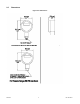
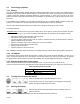
Interface: Update Rate: Minimum Output:: Maximum Output: Reverse Voltage Protected: 3 feet of cable with strain relief same as display At least -2.5% of full scale At least 102.5% of full scale Yes Figure 5-1: Load/power curve for 4-20 mA output 5.3 Wiring Codes And Schematics 5.3.1 Wiring To The Terminal Blocks Although each digital pressure gauge comes completely wired with 3 feet of cable, it may be desired to remove the cable and directly wire to the terminal blocks on the analog circuit board.
5.3.2 Limit Option Figure 5-3: Wiring code for limit option 5.3.3 0-5 VDC Output Option Figure 5-4: Wiring code for 0-5 VDC output option 5.3.
5.3.5 4-20 mA Output Option Figure 5-6: Wiring code for 4-20 mA output option 5.4 Explanation Of Limits Limits allow the instrument to signal both the operator (via the front panel indicators) and other equipment (via the contact relays) that the pressure is within or outside of a specified range. Limit 1 is a "low limit" and Limit 2 is a "high limit." If the pressure applied to the instrument is less than the setpoint entered for Limit 1, the limit will turn "on.
• • • • • • • • • Remove the center screw from the rear of the unit and gently remove the electronics from the housing. Apply power via the integral cable and run to an appropriate instrument. FORCE ZERO -Select the Analog Output Zero Scale ("A-LO) menu item by following the directions in "FIELD SELECTABLE FEATURES" in Chapter 6. When the display says "DONE", the microprocessor has forced the analog output to 0 VDC or 4 mA.
To change a feature with the Setup Menu: Make sure the instrument is turned off. Press the [On/Off] button. While unit is checking the display (lighting all LCD segments simultaneously), press and hold down the [Zero] button. The display now reads "L-LO”, which is the first item of the Setup Menu. Release the [Zero] button. Pressing and releasing the [Zero] button will scroll down through the available Setup Menu items.
6.3 Low Limit Setpoint ("L-LO") Menu Item The Low Limit Setpoint ("L-LO”) menu item determines the pressure reading below which Limit 1 will turn "on". This value is displayed and modified in the user-selected engineering units specified in the Engineering Units ("UNIT”) menu item. If the Engineering Units ("UNIT”) menu item is changed, the value stored in the Low Limit Setpoint ("L-LO”) menu item will automatically convert the new engineering units.
6.5.5 [Clear] Button Disable Feature This feature disables the ability to clear the high and low data values with the [Clear] button. The ability to restore the calibrated zero is also disabled. When the [Clear] button is pressed, the display momentarily reads "-EO-" which indicates that the button has been disabled via the Enable Options menu item. NOTE: The high and low data values may also be cleared by turning the unit off and back on, unless the Always-On feature is used. 6.
Table 7: Available Units for "M" Pressure Reference Setting ADC PSI DUAL 6.8 Engineering Unit I Comment for factory use only PSI inHg {<0 PSI) or PSI > 0 PSI) Analog Output Zero Scale ("A-LO") Item The Analog Output Zero Scale ("A-LO”) menu item forces the analog output to either 0 Volts or 4 mA, then displays "DONE" on the display. For more information on trimming the analog output, see "Trimming Of Analog Outputs" in Section 5.6. 6.
"HELP 23”: Self-test error. The engineering unit conversion that you selected cannot be rendered on a 4 digit display. For example, consider the case of an instrument with a range of 10000 PSI. If you were to select mbar in the Engineering Units ("UNIT”) menu item the instrument would signal this error. This is because 10000 PSI equals 689475 mbar, which cannot be shown on a 4 digit display. "HELP 27”: Non-volatile memory write error. “HELP 28”: Non-volatile memory read error.
Figure 8-1: Power adapter specification CHAPTER 9 WARRANTY REPAIR POLICY Limited Warranty On Products Any Cooper Instruments product which, under normal operating conditions, proves defective in material or in workmanship within one year of the date of shipment by Cooper will be repaired or replaced free of charge provided that a return material authorization is obtained from Cooper and the defective product is sent, transportation charges prepaid, with notice of the defect, and it is established that th