
User guide


TSFM 500 DC 2 32-1101 REV 2 710
In general, the controller can be mounted at any angle, although extra care should be taken during installation and
operation.
3.2 Setting up the Controller
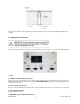
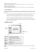
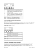
The power plug and controller cable must be connected to the rear of the controller, as shown in the illustration below:
1. Fuse
2. STAND / Controller Cable Connector
Plug one end of the cable into this connector, and the other end into the connector adjacent to the motor on the test
stand. If this cable is not connected, the error message ENCODER ERROR will be shown on the display and the test
stand cannot be operated.
3. PC / PC Control Connector
Plug one end of the 09-1056 serial cable into this connector, and the other end into a serial connector on a computer.
4. Power Plug Receptacle
Plug the power cord in here.
5. ENCODER / Travel Indication Connector