TSFM500-DC Digital Controllers Series DC User’s Guide
Table of Contents 1 LIST OF INCLUDED ITEMS....................................................................................................................1 2 OVERVIEW ...............................................................................................................................................1 3 MECHANICAL SETUP & SAFETY.........................................................................................................1 4 CONTROLS LAYOUT ...........................................
Thank you for purchasing a Mark-10 Series DC digital test stand controller, designed for use with Mark-10 motorized test stands. Mark-10 test stands and controllers are ruggedly built for many years of service in laboratory and industrial environments. This User’s Guide provides setup, safety, and operation instructions for the digital controller. Dimensions and specifications are also provided. Instructions for the test stand may be found in a separate user’s guide.
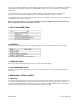
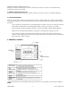
In general, the controller can be mounted at any angle, although extra care should be taken during installation and operation. 3.2 Setting up the Controller The power plug and controller cable must be connected to the rear of the controller, as shown in the illustration below: 1. Fuse 2. STAND / Controller Cable Connector Plug one end of the cable into this connector, and the other end into the connector adjacent to the motor on the test stand.
Applicable for TSTM / TSTMH test stands only Plug one end of the RJ11 cable into this connector, and the other end into the connector on the underside of the mechanism housing on the test stand. 6. GAUGE / Gauge Cable Connector Plug one end of the 09-1143 cable into this connector, and the other end into a Series 5, Series BG or BGI gauge. 3.
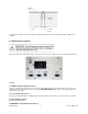
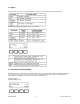
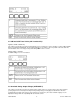
5 TEST PARAMETER SETUP This section provides configuration instructions for each test parameter. The initial Test Parameter Setup screen appears as follows: When the parameters have been configured as desired and are ready to be saved, press ESC to exit Test Parameter Setup. The screen will show SAVE CHANGES? Pressing YES will save the changes and the display will revert to current status. Pressing NO will not save the changes and return to the Test Parameter Setup menu.
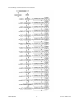
The following is a flow chart for the menu structure: TSFM 500 DC 5 32-1101 REV 2 710
5.1 Speed Independent speeds can be set for both directions of movement. The parameters are labeled as follows: Default speed settings and available speeds are as follows: 5.2 Auto Return (AUTO RETURN) With this feature, the test stand moves to a limit switch, load set point, or travel limit (TSTM / TSTMH only), whichever occurs first, and stops. Then, the test stand returns to the other limit and stops. The test speed is dictated by the independent speed settings.
5.3 Cycling (CYCLES) This setting allows the user to configure the number of cycles through which the test stand will sequence. One cycle consists of the test stand moving to a limit switch, load set point, or travel limit (TSTM / TSTMH only), whichever occurs first, at the specified speed, stopping for the specified amount of dwell time, and returning to the other limit at the specified speed. Default setting: 00000 (off) Available settings: 00000 – 99999 5.
5.5 CW and CCW Travel Limits (CW L and CCW L) Applies to TSTM / TSTMH only This setting corresponds to the rotational travel distance the test stand moves before stopping or cycling. CW and CCW limits are programmed individually. The programmed distances are relative to the zero position of the test stand. The travel indicator can be zeroed by pressing and holding STOP for three seconds. Default setting: 1 revolution Available settings: ± 2,777.77 revolutions 5.
Default setting: OFF Available settings: ±1V, ±2V, ±4V, OFF 5.7 Overload Settings (C OVERLOAD and T OVERLOAD or CW OLOAD and CCW OLOAD) The setting corresponds to the percentage of full scale of the force or torque gauge at which test stand travel stops. For example, a setting of 80% for a 50 lb capacity force gauge would stop test stand motion when 40 lb is reached. Independent settings may be programmed for both load directions (tension and compression, or CW and CCW).
5.9 Baud Rate (BAUD RATE) This setting corresponds to the baud rate setting of the computer program controlling the test stand. Default setting: 19200 Available settings: 1200, 2400, 4800, 9600, 19200, 38400, 57600, 115200 5.10 Stop Bits and Parity (STOP & PAR) This setting corresponds to the stop bits and parity settings of the computer program controlling the test stand.
5.11 Units of Speed (UNITS) Default setting: in/min or RPM Available settings: in/min, mm/min or RPM, °/sec 5.12 Programmable Button Function (KEYS) Three button function modes are available: 1. Maintained The test stand will move continuously once the button has been pressed. Subsequently pressing the UP, DOWN, or STOP during a test will stop motion. 2. Momentary The test stand will move only if the button is held down. Releasing the button will stop movement immediately. 3.
5.13 Default Settings (DEFAULT?) This setting provides a quick return to factory settings, as follows: UP SPEED: DN SPEED: AUTO RETURN: CYCLING: CW L: CCW L: OVERLOAD V: OVERLOAD: CONTROL: BAUD RATE: STOP & PAR: UNITS: PASSWORD: KEYS: Depends on test stand Depends on test stand off 00000 (off) 1 revolution 1 revolution OFF 100% CONSOLE 19200 8-1n Depends on test stand 0000 (off) maintained Default setting: off Available settings: off, on 5.
6 OPERATING MODES 6.1 Mode Overview Series DC controllers can be operated in three modes: 1. Basic Mode Manual control of test stand movement. 2. Auto Return Mode Test stand moves to a limit switch, load set point, or travel distance (TSTM / TSTMH only), whichever occurs first, then reverses and moves at maximum speed to the other limit, whichever occurs first. 3. Cycling Mode Test stand cycles between limits at the selected speed, and pauses at each limit for a selected period of time. 4.
6.2 Menu Navigation At power-up, the display will show the operation screen for whichever mode was used last. The display will appear as one of the following: Basic & Auto Return Modes: Cycling Mode: PC Mode: Appears the same as in Basic and Auto Return modes. Pressing menu will enter Test Parameter Setup. If a password has been programmed, the display will prompt the following: The password is a four digit number.
Holding down the button for more than 0.5 seconds will enter Momentary mode, at which time an audible indicator will sound and the LED indicator on the button pushed will be illuminated. A short tap on the button will operate the test stand in Maintained mode. Pressing STOP during Maintained mode will stop motion. To resume the test, press UP or DOWN again. Pressing EMERGENCY STOP will immediately stop motion in any mode. To release, twist the button counterclockwise until it assumes its original position.
6.4 Cycling Mode This mode cycles the test stand between limit switches, load set points, or travel distance set points (TSTM / TSTMH only), whichever occurs first. One cycle consists of the following steps: 1. Test stand moves to a limit at the specified speed. 2. Test stand stops for the specified amount of dwell time. 3. Test stand reverses direction, returns to the other limit at the specified speed, and stops. A cycling sequence can be initiated from any position and can start in either direction.
Once the sequence has been completed, the screen will revert to the number of cycles programmed originally. To begin another cycle test, press UP or DOWN. Travel indication and limit switch operation is the same as in Basic Mode. 6.5 PC Mode The test stand may be controlled by a computer through the Series DC controller via serial communication. A list of supported ASCII commands is provided below. All commands must be lowercase.
The 09-1143 cable is needed to communicate between a Mark-10 gauge and the controller. The 09-1056 serial cable is needed to communicate between a computer and the controller. Baud rate, stop bits and parity must be programmed in the stand to correspond with the computer program’s settings. Details on this are provided in Section 5. While in PC control, if any parameters are changed on the controller, these settings will be ignored, except if Auto Return or Cycling are turned on.
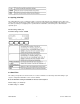
9 DIMENSIONS in [mm] 10 WARRANTY Limited Warranty on Products Any Cooper Instruments product which, under normal operating conditions, proves defective in material or in workmanship within one year of the date of shipment by Cooper will be repaired or replaced free of charge provided that a return material authorization is obtained from Cooper and the defective product is sent, transportation charges prepaid, with notice of the defect, and it is established that the product has been properly installed, mai
* Technical description of the defect: In order to properly repair a product, it is absolutely necessary for Cooper to receive information specifying the reason the product is being returned. Specific test data, written observations on the failure and the specific corrective action you require are needed.