
User guide
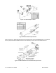
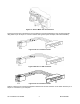
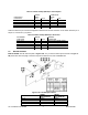
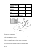
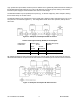

Table 2.1. Meter Hookup (RS-232) to the Computer
METER
(DCE)
COMPUTER
(DTE)
PIN SIGNAL/
FUNCTION
RJ-11 RJ-12 D9 D25
RTS, meter from computer 1 2 7 4
TX, meter = RX, computer 2 3 2 3
RX, meter = TX, computer 3 4 3 2
Return 4 5 5 7
NC (not connected) 1,6 (all others)
Table 2.2 shows the pin connection assignments between the RS-232 connection on the meter and the 9-pin or
25-pin “D” connectors of your printer.
Table 2.2. Meter Hookup (RS-232) to the Printer
METER
PIN SIGNAL/
FUNCTION RJ-11 RJ-12
PRINTER
FUNCTIONS
RTS, meter 1 2 Data Terminal Ready (DTR)
TX, meter 2 3 Received Data (RXD)
RX, meter 3 4 Not Connected
Return 4 5 Signal Return
NC (not connected) 1,6
2.3 RS-485 Hardware
INSTALLATION: The RS-485 card (refer to Figure 2-5A, or if you have an older option card refer to Figure 2-
5B) is the same size and plugs in the same ways as the RS-232 card, refer to Section 2.2.
Figure 2-5A. RS-485 Option Board
JUMPER
RS485
HALF DUPLEX
RS485
FULL DUPLEX
S1-A OPEN OPEN
S1-B CLOSE OPEN
S2-A CLOSE CLOSE
S3-A * *
CF 125 INFINITY SC GUIDE 4 M1519/N/0605