
User guide
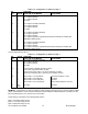
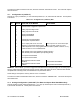
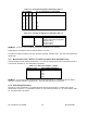

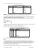
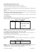
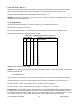
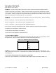

Table 11.9. Average Configuration (“AVG.CNF”) Bits 3-0
BIT NUMBER
3 2 1 0
NO. OF READINGS IN AVERAGING
0 0 0 0 1
0 0 0 1 2
0 0 1 0 4
0 0 1 1 8
0 1 0 0 16
0 1 0 1 32
0 1 1 0 64
0 1 1 1 128
1 0 0 0 256
Table 11.10. Average Configuration (“AVG.CNF”) Bits 7-4
BIT NUMBER VALUE FUNCTION
4 0
1
Averages with ABC filter
Averages with fixed (normal) filter
5 0 N/A (set to zero)
6 0 N/A (set to zero)
7 0 N/A (set to zero)
EXAMPLE: You want to use the ABC filter and have 128 readings in the average.
These settings correspond to a binary value of 00000111=07 Hex.
To write these values to RAM of meter #15, send the command *15P0E07<CR>. The meter will respond with
15P0E<CR>.
11.9 Measurement Time (“GATE T”) For Rate and Square Root Rate Modes Only
This item pertains to Rate and Sq Rt Modes only. It is 1 byte (2 characters) and uses command prefixes G, P,
R, and W with the suffix 18. The data format is as follows:
Table 11.11. Gate Time (“GATE T”) Values
“GATE T’ Value GATE TIME IN SECONDS
0 0.03
1 0.10
2 0.30
3 1.00
4 3.00
EXAMPLE: You want the RATE measurement time of your meter to be 1 s. To write this value to RAM of
meter #15, send the command *15P1803<CR>. The meter will respond with 15P18<CR>.
11.10 Pulsed Setpoint Number
This item is 1 byte (2 characters). It specifies the single setpoint to which the AL TI (alarm time or pulse
duration-Refer to Section 11.11) parameter pertains. It uses command prefixes G, P, R, and W with the suffix
20. The data format is as follows:
CF 125 INFINITY SC GUIDE 59 M1519/N/0605