
User guide
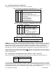
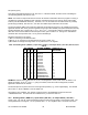
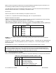
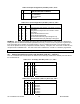
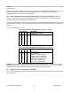
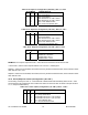
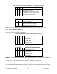
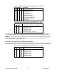
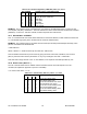

Table 10.30. Serial Configuration (“SER.CNF”) Bits 7,6 5, and 4
BIT NUMBER
7 6 5 4
ALARM 2 (SP 4) CONFIGURATION
x x 0 0 No parity (automatically reset to two stop
bits to get ten-bit characters)
x x 0 1 Odd parity
x x 1 0 Even parity
x x 1 1 Not used
x 0 x x One stop bit
x 1 x x Two stop bits
EXAMPLE: The computer sends “*15W1856<CR>”; this writes into the EEPROM memory of meter #15 hex
“two stop bits, odd parity, 19200 baud”. The meter will switch to these choices whenever a hard reset is initiated
(“RESET2”). If “BUS.3=1” has been entered, the meter responds with “15W18<CR>”.
10.17 RS-485 Meter “ADDRES”
This “1A” command suffix uses 2 HEX-ASCII characters for the device address, but that number is limited to the
1 to 199 decimal range (many more numbers than the 32-device hardware limit).
EXAMPLE: The computer wants to renumber meter #15 HEX (#21 decimal) to #25 HEX (#37 decimal); it then
puts the new address into EEPROM with:
“*15W1A25<CR>”
Which, if “BUS.3=1”, would be echoed by the meter with “15W1A<CR>”.
This new address would then be put into action by giving the meter a hard reset, “RESET2”, from the front-
panel, by external contact closure (see Section 10.18), or by sending the reset with: “*15Z04<CR>”.
That meter will no longer answer to the “15” hex address; it now responds commands preceded by “*25”.
10.18 Data Format (“DAT FT”)
The “1B” command suffix uses two nibbles of data to describe how the meter will respond to the “V01”
command, as explained in Appendix A (“DAT.8” is the MSB).
“x” is used to show either “1” or “0”.
Table 10.31. Data Format (“DAT FT”), Bits 3, 2, 1, and 0
BIT NUMBER
3 2 1 0
SELECTS
x x x 0 Do not send Alarm Status
x x x 1 Send Alarm Status Char
x x 0 x Do not send PEAK/VALLEY status
x x 1 x Send PEAK/VALLEY status
x 0 x x Do not send current reading value
x 1 x x Send current reading value
0 x x x Do not send filtered reading value
x x x x Send filtered reading value
CF 125 INFINITY SC GUIDE 46 M1519/N/0605