
User guide
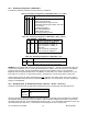
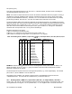
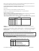
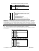
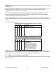
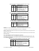
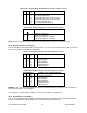
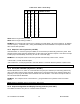
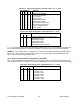
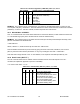

Table 10.22. Alarm 2 (SP 4) Configuration (“AL CNF”), Bits 5, 4, and 3
BIT NUMBER
4 3
CONFIGURATION
x 0 AL 2 (SP 4) active above
5
x
x x 1 AL 2 (SP 4) active below
x 0 x Out transistor #4 on if AL 2 (SP 4) active
x 1 x Out transistor #4 off if AL 2 (SP 4) active
0 x x AL 2 uses unfiltered value
1 x x AL 2 driven from filtered value
Table 10.23. Alarm Configuration (“AL CNF”), Bits 7 and 6
BIT NUMBER
6
CONFIGURATION
x 0 Enable AL 1 and AL 2
x 1 Disable AL 1 and AL 2
0 x Alarm reset at pin P2-11 disabled
1 x Alarm reset at pin P2-11 enabled
7
NOTE: Pin P2-11 is shared with the external print command (Refer to “BUS FT” in Section 10.19).
10.11 Alarm Functions (“AL FNC”)
The “12” command suffix encodes the controls for Alarm 1 (SP 3) in the LSN and for Alarm 2 (SP 4) in the LSN
and for Alarm 2 (SP 4) in the MSN of the data byte:
Table 10.24. Alarm 1 Function (“AL FNC”), Bits 3, 2, 1 and 0
BIT NUMBER
3 2 1 0
ALARM 1 (SP3) CONFIGURATION
0 x 0 0 Process (no deviation)
0 x 0 1 High deviation
0 x 1 0 Low deviation
0 x 1 1 Band deviation
0 0 x x Unlatched Alarm
0 1 x x Latched Alarm
Table 10.25. Alarm 2 Function (“AL FNC”), Bits 7, 6, 5 and 4
BIT NUMBER
7 6 5 4
ALARM 2 (SP4) CONFIGURATION
0 x 0 0 Process (no deviation)
0 x 0 1 High deviation
0 x 1 0 Low deviation
0 x 1 1 Band deviation
0 0 x x Unlatched Alarm
0 1 x x Latched Alarm
EXAMPLE: The computer wants the alarms of meter #15 HEX both latching, with Alarm 1 high deviation and
Alarm 2 band deviation. The message is:
“*15P1275<CR>”, and the meter would echo “15P12<CR>” if “BUS.3=1” had been set.
10.12 Alarm Delay: (“AL RDG”)
This “33” command suffix data is straight forward binary coding of the number of alarm readings before alarm
activation, using MSN and LSN for Alarm 1 (SP 3) and Alarm 2 (SP 4) respectively.
CF 125 INFINITY SC GUIDE 43 M1519/N/0605