DFI INFINITY SERIAL COMMUNICATIONS GUIDE www.cooperinstruments.
TABLE OF CONTENTS 1. INTRODUCTION ....................................................................................................................................... 1 2. HARDWARE.............................................................................................................................................. 1 2.1 Definition of Terms....................................................................................................................... 1 2.2 RS-232 Hardware ...................
8.5.1 Error Response Format......................................................................................................... 23 8.5.2 Error Message ....................................................................................................................... 24 8.5.3 Description............................................................................................................................. 24 8.6 Status Character Formats...........................................................
11.3 Display Mode ............................................................................................................................. 54 11.4 Configuration 1 (“CNFG 1”) ....................................................................................................... 55 11.5 Configuration 2 (“CNFG 2”) ....................................................................................................... 55 11.6 Configuration 3 (“CNFG 3”) .......................................................
1. INTRODUCTION This guide is intended to facilitate digital communication between your computer (or other controlling device) and one or more meters. This digital-communications guide is provided for use with any of the meters OWNER’S GUIDES for Process, Strain gauge, Temperature, Universal, Rate meter/totalizer, Batch controller or Clock, which provide details of all applicable inputs, connections, option, push button controls and programming procedures. 2. HARDWARE 2.
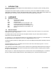
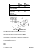
Figure 2-1A. RS-232 Option Board Figure 2-1B Older RS-232 Option Board Refer to Figure 2-1B. When interfacing the meter to devices that do not have handshaking lines, i.e. RTS/CTS, the S1-A jumper should be installed. However, when interfacing to a PC, the S1-A should be removed. Figure 2-2.
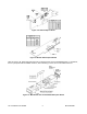
Figure 2-3. Rear of Meter with J4 Connection Figures 2-4A and Figure 2-4B show the four-wire RS-232 connections between the host computer/controller using either a 9-pin or 25-pin “D” connector and the meter (point-to-point full duplex, with RTS handshake). Figure 2-4A. RJ-11 to D9 Connector Figure 2-4B. RJ-11 to D25 Connector Figure 2-4C. RJ-12 to D9 Connector Table 2.
Table 2.1. Meter Hookup (RS-232) to the Computer PIN SIGNAL/ FUNCTION RTS, meter from computer TX, meter = RX, computer RX, meter = TX, computer Return NC (not connected) METER (DCE) RJ-11 1 2 3 4 COMPUTER (DTE) D9 D25 7 4 2 3 3 2 5 7 (all others) RJ-12 2 3 4 5 1,6 Table 2.2 shows the pin connection assignments between the RS-232 connection on the meter and the 9-pin or 25-pin “D” connectors of your printer. Table 2.2.
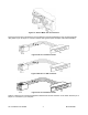
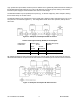
RS485 HALF DUPLEX JUMPER (CLOSE FOR TERMINAL RESISTOR) S3-B CLOSE S3-C (CLOSE FOR TERMINAL * RESISTOR) S3-D CLOSE S3-E (CLOSE FOR RTS OPEN TRUE) S4 (CLOSE FOR * CONTINUOUS MODE) Note: * means optional, select as required. RS485 FULL DUPLEX OPEN * OPEN OPEN * Figure 2-5B. Older RS-485 Option Board Figure 2-5B shows the card outline and the pin designators for the connectors. There are 4 jumper-selected features.
Logic symbols are opto-isolated, and drive power is obtained from a galvanically-isolated transformer winding so that the differential signals (minimum ±2 V) will not be altered by an external ground; earthing of the external transceiver power supply is recommended to limit common-mode voltage. The RS-485 hardware may be operated point-to-point (e.g., as RS-422 equipment), OR in multipoint, sharing the bus wires with up to 32 other meters.
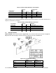
Table 2.4. Full-Duplex Hookup to the Computer PIN SIGNAL/ FUNCTION +TX -TX +RX -RX N/C or RTN N/C METER (DCE) RJ-12 NEW RS-485 1 3 2 4 - COMPUTER (DTE) D9/D25 OLDER RS-485 BD 1 2 4 5 3 6 (SEE MFG DWG) (SEE MFG DWG) (SEE MFG DWG) (SEE MFG DWG) (SEE MFG DWG) Both HALF DUPLEX (Figure 2-6) and FULL DUPLEX RS-485 (Figure 2-7) communications require a 6-wire RJ12 plug to be connected to the RJ-12 jack at the rear of the meter.
Pressing the ‘MENU’ button saves your choices and advances to “ADDRES”. This is used to set in an RS-485 device from address 0 to 199 and is accomplished by pressing the ‘MIN’ button to advance the digit position and pressing ‘MAX’ button to change values. Note: For RS-232, skip over this by pressing the ‘MENU’ button. If the communication link is in place, no more pushbutton programming is needed: the computer takes over at this point. Follow the prompts and selections on that screen. 3.
4.7 Full Duplex Two channels (e.g., two twisted pairs) with bi-directional data flow at any time (one simplex channel in each direction). 4.8 RS-232 (CCITT V.24) Bipolar ±5 to ±15 V point-to-point transmission for short distances and moderate data rates. The meter operates with full-duplex RS-232, with two wires (RX and TX), plus a common ground, to transmit baud in either direction.
To make the best use of the available storage, all possible bit sequences should be used, so each nibble can have 16 different values (not just the ten of decimal notation). These 6 values are symbolized by 0-9 and A-F, the hexadecimal code.
Table 4.2 Meter Receiving Voltages OPTION TYPE RS-232 RS-422 OR 485 “1” BIT/MARK OR STOP BIT -3 > A > -15 V A< (B-0.2 V) “0” BIT/SPACE OR START BIT +3 < A < +15 V A > (B+0.2 V) Table 4.3. Meter Transmitting Voltages OPTION TYPE RS-232 RS-422 or 485 “1” BIT/MARK OR STOP BIT -6 > A > -7 V A < (B-2 V) “0” BIT/SPACE OR START BIT +6 < A < +7 V A > (B+2 V) The RS-422/485 transmissions from the meter are 3-state, and both receive and transmit are zener-protected. 4.
Figure 6-1. Character Waveform The rising edge of the start bit of the next character may occur at any time after the end of the last stop bit. 7. CLASSES OF OPERATION There are two (2) classes of operation associated with meter serial communications: Point-to-point and Multipoint. (Refer to section 10.19 for Process, Temperature, Strain Gauge and Universal meters and Section 11.25 for Rate Meter, Totalizer and Batch meters.) 7.
7.2 Multipoint A device address from 0 to 199 is included in the COMMAND or RESPONSE message. By using the addressing capabilities, collision on the bus can be avoided. If “00” is used for the address on multiple units, they will all receive the COMMAND but will not respond. This is issued to avoid collisions on the bus. There are two (2) modes available in the class; COMMAND MODE and ALARM MODE. NOTE: NO RTS handshaking is available with Multipoint. 7.2.
7.4 The Meter As A Double Tasking Remote Meter The Process, Strain Gauge, Temperature and Universal meters can be configured as a double tasking remote indicator/controller. This is accomplished by transmitting any value (In HEX format Only!) from “-99999 to 999999” (and any decimal point position between 1 to 6) to the meter. The value transmitted will be the meter’s Reading Value, which allows you to display any value desired and assign a setpoint as well as set up the value of this setpoint.
8. COMMAND AND RESPONSE STRUCTURE 8.1 8.1.1 Message String “Data” and “Non Data” Each of the many types of messages between computer or printer and the meter is transmitted or received as a string of ASCII characters. There characters are classified as “DATA” and NON DATA”. “DATA” is the string of measurement or non-measurement values (see Section 8.2 and 8.3) and can be classified as: : hexadecimal based values. Each nibble is converted to the ASCII character and transmitted or received.
where nn = device address from 01 to C7 (hex) = 01 to 199 decimal. NOTE: Response detail is given in Section 8.8 and 8.9. 8.2.2 General Command Structure The meter can be commanded to “read”, i.e. to transmit (send) data from either the nonvolatile memory (EEPROM) or from the volatile working memory (RAM). The meter can also be commanded to “write”, i.e. store new values for data processing or meter control.
b) Multipoint mode: *nnccc[hh] For “Y” Command (Process, Strain Gauge, Temperature and Universal meters only): Remote Display a) Point-to-point mode: *Y01 b) Multipoint mode: *nnY01 Remote Indicator Controller a) Point-to-point mode: *Y02 b) Multipoint mode: *nnY02 Where “*” is the selected Recognition Character, you may select any ASCII table symbol from “!” (hex address “21”) to the right-hand brace (hex “7D”) except for the caret “^”, “A”, “E”, which are reserv
Command Suffix V 01 X 01 Y 01 Z 01 D 02 E 02 R, W 02 U 02 X 02 X Y02 Z 02 D 03 E 03 R, W 03 U 03 X 03 Z 03 D 04 E 04 R, W 04 X 04 Z 04 D 05 E 05 G, P, R, W 05 Z 05 G, P, R, W 07 G, P, R, W 08 G, P, R, W 09 G, P, R, W 0A G, P, R, W 0B G, P, R, W 0C G, P, R, W 0E G, P, R, W 10 G, P, R, W 11 G, P, R, W 12 G, P, R, W 13 R, W 14 R, W 15 G, P, R, W 16 G, P, R, W 17 R, W 18 G, P, R, W 1A G, P, R, W 1B G, P, R, W 1C R, W 1D G, P, R, W 1E G, P, R, W 1F R, W 20 G, P, R, W 21 G, P, R, W 22 G, P, R, W 23 G, P, R, W 24
Command G, P, R, W G, P, R, W R, W R, W R, W R, W Suffix 40 41 42 43 44 45 Item affected RAM or EEPROM BLOCK A RAM or EEPROM BLOCK B EEPROM BLOCK C EEPROM BLOCK D EEPROM BLOCK E EEPROM BLOCK F #Char 60 38 20 - Section 10.25.1 10.25.2 10.25.
COMMAND E G,P,R,W X Z E G,P,R,W Z G,P,R,W G,P,R,W G,P,R,W R,W G,P,R,W G,P,R,W G,P,R,W G,P,R,W G,P,R,W SUFFIX 04 04 04 04 05 05 05 06 07 08 09 0A 0B 0C 0D 0E G,P,R,W 11 G,P,R,W 12 G,P,R,W 13 G,P,R,W G,P,R,W G,P,R,W G,P,R,W G,P,R,W R,W R,W G,P,R,W G,P,R,W G,P,R,W G,P,R,W R,W G,P,R,W G,P,R,W G,P,R,W G,P,R,W G,P,R,W R,W G,P,R,W G,P,R,W G,P,R,W G,P,R,W G,P,R,W G,P,R,W G,P,R,W G,P,R,W R,W R,W R,W R,W R,W G,P G,P,R,W 14 15 16 17 18 19 1A 1B 1C 1D 1E 1F 20 21 22 23 24 25 26 27 28 29 2A 2B 2C 2D 2E 2F 30 31
COMMAND G,P SUFFIX 41 ITEM AFFECTED RAM Block B R,W 41 EEPROM Block B G,P,R,W 42 R,W R,W 43 44 RAM or EEPROM Block C (only for Batch mode) EEPROM Block D EEPROM Block E # CHAR Batch and (SQ RT): 34 Rate:36 Batch and (SQ RT): 50 Rate: 52 22 SECTION 11.32 11.32 12 18 11.32 11.32 11.32 NOTES: 1. Each BLOCK is the string o HEX-ASCII data that is produced by the concatenation of the data for single items listed below.
2. Suffixes 0E and 0F are not used: the meter will respond to these with an error message. 3. The meter, upon completion of a BLOCK PUT (into RAM) Command, goes to soft reset which does not copy EEPROM data into RAM. 4. Upon completion of a BLOCK WRITE (into EEPROM) Command, however, the meter goes to hard reset copying the data from EEPROM into the working RAM. Single PUT (or WRITE) commands to not interrupt the measurement process of the meter, even when the changes are to scale or offset values. 5.
2) For the Rate meter/totalizer or Batch meters: [Sa][S][SP][S][SP][S][SP][S][hh][] b) For “X” Command: [hh][] For Type (3) Commands: [hh][] Where “nn” is the meter’s address HEX format and is omitted from the response format if the communication is in the point-to-point mode. “ccc” is the three (3) character command prefix letter and it’s suffix number. “d” is one ASCII character.
?ee[] where “?ee” is the special code indicating an error has occurred as follows: 8.5.2 Error Message Table 8.4 Error messages 1 2 3 4 5 6 7 8 9 10 8.5.3 ERROR MESSAGE Command Error Format Error Checksum Error Parity Error Calibration/Write Lockout Error EEPROM Write Lockout Error Serial Device Address Error Decimal Point Error Serial Recognition Error Invalid Character(s) used in with Y01 Command CODE ?43 ?46 ?48 ?50 ?4C ?45 ?56 ?56 ?56 ?56 Description 1.
2. When in multipoint mode, the meter will test the command’s address with the one previously assigned after the recognition character has been matched. The meter will not respond to the command if addresses do not match, even if an error has occurred. 3. If the meter is in the Menu or Setpoint mode and receives any transmitted data, it quits that routine, displays “SERIAL” for up to two seconds, completes its Communication job, and then resets the meter, i.e.
CHARACTER M N O P Q R S T U V W X Y Z a b c d e 8.6.
Table 8.8 Description of Special Characters Used for Communication Commands CHARACTERS 2 PROCESS, STRAIN GAUGE, TEMP.
Command format *15G1A Response format 15G1A15 3. Write “VLT” as units of measure into the EEPROM of the meter in the point-to-point mode: Command format *W1F564C54 Response format W1F where 56, 4C, 54 are the three HEX ASCII values for V, L, and T respectively. 4. Read alarm status character from the meter number 15 HEX: Command format *15U01 Response format 15U01@ where “@” is the alarm status character, decoded using Table 8.5 or 8.6. 5.
c) meter’s address is “15 HEX” if it is used in the multipoint mode d) no line feed or checksum characters are included 1. Read serial recognition character from EEPROM in point-to-point mode: Command format *R24 Response format R242A (Since “2A” is HEX ASCII value of “*” in the table). 2. Read serial address from the RAM of the meter number “15 HEX” in the multipoint mode: Command format Response format *15G1D 15G1D15 3.
10. Read block of data from EEPROM in point-to-point mode when the meter is operating in Batch Mode: Command format Response format *R42 R4244114 where 44 HEX is the TOTAL value, 11 HEX is the Batch count, and 4 HEX is the BAT NO. 9. METER BUS RESPONSE As detailed before, the meter can receive and transmit at baud rates up to 19,200.
1. For Process, Strain Gauge, Temperature and Universal meters: a) Slow mode = 0 to 300 ms b) Fast mode = 0 to 100 ms 2. For Ratemeter/totalizer, Batch meter with chunk transmissions: a) Rate mode = 0 to 35 ms b) Batch mode = 0 to20 ms c) Square-root mode = 0 to 40 ms 3.
transmission. Specifically, if command “^AE” is transmitted, it will cause the meter to switch to COMMAND mode. To be able to communicate with the meter when in Continuous Mode, do the following: 1. Transmit “X-OFF” character or make “RTS” line false. 2. Transmit “^AE” command. Now your meter is in Command Mode. 3. Do the communication with the meter. 4. Use “P1C” command to change BUS FORMAT (see Section 10.19 for Process, Strain Gauge, Temperature and Universal meters and Section 11.
To use this command for the Process, Strain Gauge, Temperature or Universal meters, bit “BUS.8” must “=1” (Refer to Section 10.23). To use this command for the Rate meter/totalizer or Batch meters, bit “CF4.4” must equal “1” (Refer to Section 11.7). NOTE: Special attention and care should be taken when this feature is used with the multipoint mode and there is more than one meter on the bus.
3. When “W” command is given, a reset is necessary to initiate the command. 4. “X” in bit pattern information means the bit is not related to that parameter. 5. Each byte consists of 8 bits. 6. Each byte consists of 2 nibbles; Most Significant Nibble (MSN) and Least Significant Nibble (LSN) 10.1 Lockout Bytes “R” or “W” followed by “01”, “02”, “03”, or “04” send to EEPROM or receive from EEPROM the 8 bits of each of the four lockout bytes.
LOCKOUT =1 L2C.8=0 =1 L3 CNF: L3C.1=0 =1 L3C.2=0 =1 L3C.3=0 =1 L3C.4=0 =1 L3C.5=0 =1 L3C.6=0 =1 L3C.7=0 =1 L3C.8=0 =1 L4 CNF: L4C.1=0 =1 L4C.2=0 =1 L4C.3=0 =1 L4C.4=0 =1 L4C.5=0 =1 L4C.6=0 =1 10.2 FUNCTION Locked Unlocked Locked CORRESPONDING ITEM FIL.
Table 10.3. Input Range for Thermocouple BIT NUMBER 3 2 1 0 0 0 0 0 0 0 0 1 1 0 1 0 0 0 1 1 0 1 0 0 0 1 0 1 0 1 1 0 0 1 1 1 1 0 0 0 RANGE OR TYPE J K T E N DIN J R S B Table 10.4 Input Range for RTD BIT NUMBER 3 2 1 0 0 0 0 0 0 0 0 1 0 0 1 0 0 0 1 1 0 1 0 0 0 1 0 1 0 1 1 0 RANGE OR TYPE 2-wire, 0.003926 Alpha (NIST) 3-wire, 0.003926 Alpha (NIST) 4-wire, 0.003926 Alpha (NIST) 2-wire, 0.00385 Alpha (DIN) 3-wire, 0.00385 Alpha (DIN) 4-wire, 0.00385 Alpha (DIN) Linear or Ohms Table 10.5.
10.3 Reading Configuration (“RDG.CNF”) 2 Characters (2 nibbles) of data are used for all four 07 commands: Table 10.6. Reading Configuration (“RDG.CNF”), Bits 3, 2, 1, and 0. BIT NUMBER 3 2 1 0 x x x 0 x x x 1 x x 0 x x x 1 x x x 0 1 0 1 x x x x x x x x x x FUNCTION Direct entry, RDG SC, RDG OF 2-Data Point, RD.SC.
SC=(O2-O1)/(I2-I1) This value is entered/read with these “08”, 0B” and “17” command suffixes, and also used in calculating the corresponding Offsets (see Section 10.9). NOTE: True value for output scale factor is stored in its location in EEPROM. When the program is running, it combines this value with calibration scale of analog out board and stores new value in output scale’s RAM location (CALLED MODIFIED OUTPUT).
MSN are used for decimal point (referenced to the right-hand display dp position) as given in the Table 10.10. The remaining 5 nibbles (20 bits) are the magnitude (resolution one ppm). Your data might be in the form of two data points (O2,I2 and O1,I1); since the meter stores this information as separate scale and offset values, it is necessary to calculate the offset: OF=O1-SC*I1, where the scale factor SC is that calculated by the equation in Section 10.4. In Table 10.
Table 10.12 Input Configuration (“IN CNF”), Bits 4, and 3 BIT NUMBER 4 3 0 0 0 1 1 0 1 1 FUNCTION (VALID IN RTD OR TC MODES) No transmitter TC Transmitter RTD transmitter Not used Table 10.13.
EXAMPLE: The computer wants to set meter #15 hex to center the decimal point and count-by-10. It transmits “*15P0C43”. These data are put into EEPROM by using “W”, and can be read from the RAM or EEPROM by “G” or “R”: For example, commanding “*15G0C” elicits the meter response of “15R0C43” for the above configuration when a command-echo is programmed. 10.8 Filter Configuration And Number Of Samples In The Average (“FIL.
Table 10.18. Setpoint 1 Configuration (“SP CNF”), Bits 2, 1, and 0 BIT NUMBER 2 1 0 x x 0 x x 1 x 0 x x 1 x 0 x x 1 x x CONFIGURATION SP 1 active above SP 1 active below Out transistor #1 on if SP 1 active Out transistor #1 off if SP 1 active SP 1 uses unfiltered value SP 1 driven from filtered value Table 10.19.
Table 10.22. Alarm 2 (SP 4) Configuration (“AL CNF”), Bits 5, 4, and 3 BIT NUMBER 5 4 3 x x 0 x x 1 x 0 x x 1 x 0 x x 1 x x CONFIGURATION AL 2 (SP 4) active above AL 2 (SP 4) active below Out transistor #4 on if AL 2 (SP 4) active Out transistor #4 off if AL 2 (SP 4) active AL 2 uses unfiltered value AL 2 driven from filtered value Table 10.23.
Table 10.26.
Table 10.27. Output Configuration (“OUT.CNF”) Bits 4, 3, 2, 1, and 0 BIT NUMBERS 4 3 2 1 x x x x x x x x x x x 0 x x x 1 x x 0 x x x 1 x x 0 x x x 1 x x 0 x x x 1 x x x SELECTS 0 0 1 x x x x x x x x Analog output disabled Analog output enabled 0-10 V output 0-20 mA output Parallel BCD disabled Parallel BCD enabled BCD driven by display value BCD driven by PEAK value Large or desktop printers Panel printers Table 10.28. Output Configuration (“OUT.
Table 10.30. Serial Configuration (“SER.CNF”) Bits 7,6 5, and 4 BIT NUMBER 7 6 5 4 x x 0 0 x x x x x x x x 0 1 0 1 1 x x 1 0 1 x x ALARM 2 (SP 4) CONFIGURATION No parity (automatically reset to two stop bits to get ten-bit characters) Odd parity Even parity Not used One stop bit Two stop bits EXAMPLE: The computer sends “*15W1856”; this writes into the EEPROM memory of meter #15 hex “two stop bits, odd parity, 19200 baud”.
Table 10.32.
Table 10.35. Bus Format (“BUS FT”), Bits 7 and 6 BIT NUMBER 7 6 x 0 x 1 0 x 1 x FUNCTION RS-485 board not installed RS-485 board installed External print command on P2-11 disabled* External print command on P2-11 enabled* *P2-11 is shared with alarm reset command (Refer to Section 10.10, Table 10.22) The least-significant nibble of “BUS FT” should have the two least-significant bits set to zero (reserved for future checksum/line feed features).
Each letter is represented by the two HEX-ASCII characters giving its ASCII table address, from “41” to 79” (all upper and lower case letters) or the address, “20”, for a total of six transmitted characters (do not select any control characters for units-of-measure). When the desired units-of-measure to be printed have fewer than 3 characters, send the address (“20”) to put the blank(s) in the chosen spot(s).
Table 10.37. Setpoint Values, Bits 23, 22, 21, and 20 BIT PATTERN 23 22 21 0 0 0 0 0 0 0 0 1 0 0 1 0 1 0 0 1 0 0 1 1 0 1 1 1 0 0 1 0 0 1 0 1 1 0 1 1 1 0 1 1 0 1 1 1 1 1 1 SIGN AND DECIMAL POINT 20 0 1 0 1 0 1 0 1 0 1 0 1 0 1 0 1 Not used +FFFFFF. +FFFFF.F +FFFF.FF +FFF.FFF +FF.FFFF +F.FFFFF Not used Not used -FFFFFF. -FFFFF.F -FFFF.FF -FFF.FFF -FF.FFFF -F.FFFFF Not used The following 5 nibbles (HEX-ASCII characters) give the binary magnitude.
NOTE: R, W means “R” or “W” 10.25.1 BLOCK A This block consists of ten (10) items and thirty bytes (60 ASCII characters) as Table 10.39: Table 10.39. Block A (HEX ITEM SUFFIX) 26 17 25 0B 09 08 24 23 22 21 10.25.2 DESCRIPTION Analog Out Offset Analog Out Scale Input Offset Input Scale Display Offset Display Scale Setpoint 4 Value Setpoint 3 Value Setpoint 2 Value Setpoint 1 Value BYTE NO.
10.25.4 EXAMPLE: Assuming echo mode; no line feed; checksum; and point-to-point mode. 1. Read Block C from EEPROM a) And send to the meter: *R42 b) Response from the meter: 1. # of readings between each transmission=2711 (HEX) 2. Alarm Hysteresis=0001 (HEX) 3. Set Pt Hysteresis=0001 (HEX) 4. Lockout #4=E0 (HEX) 5. Lockout #3=3E (HEX) 6. Lockout #2=00 (HEX) 7. Lockout #1=3F (HEX) 2. Write Block C on to EEPROM.
Table 11.1. Lockouts LOCKOUT L1 CNF: L1C.1=0 =1 L1C.2=0 =1 L1C.3=0 =1 L1C.4=0 =1 L1C.5=0 =1 L1C.6=0 =1 L1C.7=0 =1 L1C.8=0 =1 L2 CNF: L2C1=0 =1 L2C2=0 =1 L2C3=0 =1 L2C4=0 =1 L2C5=0 =1 L2C6=0 =1 L2C7=0 =1 L2C8=0 =1 L3 CNF: L3C.1=0 =1 L3C.2=0 =1 L3C.3=0 =1 L3C.4=0 =1 L3C.5=0 =1 L3C.6=0 =1 L3C.7=0 =1 L3C.
11.2 Mode Mode is one byte of data (2 characters). It uses the prefixes G, R, and W with the suffix 07. This byte controls the operating mode of the meter as follows: 0: Batch Mode 1: Rate Mode 2: Sq Rt Mode The default value is 0, Batch Mode EXAMPLE: To set the mode to Rate for meter #15, send the command *15W0701. The meter will respond with 15W07. To reset the meter, send the command 15Z05. The meter will respond with 15Z05. 11.3 Display Mode This item is 1 byte (2 characters).
11.4 Configuration 1 (“CNFG 1”) This item is 1 byte (2 characters). It uses command prefixes G, P, R, and W with the suffix 0A. The bit pattern is as follows: Table 11.3. Configuration 1 (“CNFG 1”) Bits BIT NO.
VALUE 0 1 FUNCTION RATE AND SQ RT MODES SP 4 is active above SP 4 is active below 4 0 1 SP 5 is active above SP 5 is active below 5 0 1 SP 3 action is not delayed SP 3 action is delayed for 4 alarm readings Reset action is normal (manual) At SP 3, meter auto resets to 0; or at 0 resets to SP 3 (if Batch value is count down). 6 0 1 SP 4 Action is not delayed SP 4 action is delayed for 4 alarm readings BAT NO counts up BAT NO counts down from SP 4 if Bit No. 6 in CNFG 1 (Section 11.4) is set.
Table 11.6. Configuration 3 (“CNFG 3”), Byte 2 VALUE 0 1 2 3 FUNCTION RATE AND SQ RT MODES SP 1 output is normal (unlatched) SP 1 output is latched SP 1 output is pulsed Not used 2-3 0 1 2 3 SP 2 output is normal (unlatched) SP 2 output is latched SP 2 output is pulsed Not used 4-5 0 1 2 3 SP 3 output is normal (unlatched) SP 3 output is latched SP 3 output is pulsed SP 3 output is hysteretic (Hysteresis=SP4-SP3) in Rate/Sq. Rt.
To write these values to RAM of meter #15, send the command *15P0C31C814. The meter will respond with 15P0C. 11.7 Configuration 4 (“CNFG 4”) This item is 1 byte (2 characters). It uses command prefixes G, P, R, and W with the suffix 0D. The bit pattern is as follows: Table 11.8. Configuration 4 (“CNFG 4”) Bits BIT NO.
Table 11.9. Average Configuration (“AVG.CNF”) Bits 3-0 BIT NUMBER 3 2 1 0 0 0 0 0 0 0 0 1 0 0 1 0 1 0 0 1 0 0 1 1 0 1 1 1 0 0 NO. OF READINGS IN AVERAGING 0 0 1 0 1 0 1 0 1 0 1 2 4 8 16 32 64 128 256 Table 11.10. Average Configuration (“AVG.CNF”) Bits 7-4 BIT NUMBER 4 5 6 7 VALUE 0 1 0 0 0 FUNCTION Averages with ABC filter Averages with fixed (normal) filter N/A (set to zero) N/A (set to zero) N/A (set to zero) EXAMPLE: You want to use the ABC filter and have 128 readings in the average.
Table 11.12. Pulsed Setpoint Values VALUE 0 1 2 3 4 5 RESULT AL TI is used for analog output ramping function AL TI pertains to Setpoint 1 AL TI pertains to Setpoint 2 AL TI pertains to Setpoint 3 AL TI pertains to Setpoint 4 AL TI pertains to Setpoint 5 EXAMPLE: You want to assign Setpoint 2 to the AL TI parameter. To write this information to RAM of meter #15, send the command *15P2002. The meter will respond with 15P20. 11.11 Alarm Time (“AL TI”) This item is 2 bytes (4 characters).
For example, you want your input scale to be 15.25. This equals a squared value of 232.5625. The value excluding the decimal point is larger than 1000000. Divide 2325625 by 10 to get 232653 with HEX value of 38C73. Then do the following: 1. Set bit 23 to 1 2. The existing decimal number is 5. Add 1 to get 6. This and part 1 makes the Most Significant character as “F” value. 3. Your 3-byte HEX value = F38C73 HEX. 4. The meter interprets this as 232563 * 100=23256300.
Table 11.14 shows the decimal point value based on the decimal no.: Table 11.14. Decimal Point Values DP VALUE 0 1 2 3 4 5 6 7 DECIMAL NO. (POWER OF 10 MULTIPLIER) 0 0 -1 -2 -3 -4 -5 Not used EQUIVALENT DECIMAL POINT POSITION None FFFFFF. FFFFF.F FFFF.FF FFF.FFF FF.FFFF F.FFFFF Not used EXAMPLE: You want BAT DP to be FFF.FFF. This corresponds to 4 Hex. To write this information to RAM of meter #15, send the command *15P1104. The meter will respond with 15P11. 11.
TOTAL Reading = (Raw Total) * (TOT SC) + TOT OF RATE Reading = (Raw Rate) * (RTE SC) + RTE OF BATCH Count Reading = (Raw_Batch_Count) * (BAT SC) + B LOAD 3. In Rate mode, Rate scale and offset has no effect on the totalizing process. 4. In Square-root Mode, rate offset is applied to the rate value before the totalizing process. Therefore Total is affected by this value. EXAMPLE: You want to write a TOT OF value of 4562.33 and a TOT SC value of –324.8 to RAM of meter 15.
11.18 Set Time (“SET TI”) This item is a special 3-byte value in Hex format. It sets the time on the display when the front-panel RESET button or the corresponding external reset is activated. It uses prefixes R and W and the suffix is 1E. The data format is identical to that of the Setpoint 5 value in Section 11.17. EXAMPLE: You want to set the time to 12:30:20 of meter 15. Send the command *15W1E0C1E14. The meter will respond with 15W1E. 11.19 Output Scale This item is 3 bytes (6 characters).
11.20 Output Offset This item is 3 bytes (6 characters). It uses the prefixes G, P, R and W with the suffix 27. Bits 0 through 19 assign the value. Bits 20 through 22 assign the decimal number according to Table 11.19. Table 11.19. Output Offset Bits 22, 21, and 20 BIT NUMBER 22 21 0 0 0 0 0 1 0 1 1 0 1 0 1 1 1 1 20 0 1 0 1 0 1 0 1 DECIMAL NO. (POWER OF 10 MULTIPLIER) Not used 1 -0 -1 -2 -3 -4 -5 Bit 23 is the sign bit where 0 corresponds to a plus sign and 1 corresponds to a minus sign.
Byte 1 (Least) = seconds, Max 59 Byte 2 (Middle) = minutes, Max 59 Byte 3 (Most) = hours, Max 99 EXAMPLE: You want to assign TIME of meter #15 to 7:25:30. Send the command *15P2807191E. 2. BATCH count, BAT NO, and TOTAL. BATCH count and TOTAL are 4 bytes each, and BAT NO is 3 bytes. There is no decimal point for these items. The sign bit is the most significant bit of each item (0 for positive and 1 for negative).
Table 11.21. Serial Configuration (“SER.CNF”) Bits BIT NO. 0 VALUE 0 1 FUNCTION 1 Stop bit 2 Stop bits 1-2 0 1 2 3 No parity Odd parity Even parity Not used 3 0 1 Chunk transmission* Single, long transmission ** 4-7 1 Not used *Chunk transmission means that the meter transmits data while it is performing measurements. **A single, long transmission means that all of the data is transmitted at the same time. The meter does not do other tasks until transmission is complete.
These settings correspond to binary 00101011 = 2B Hex. Send the command *15P1B2B. The meter will respond with 151B. 11.25 Communication Bus Format (“BUS FT”) This item is 1 byte (2 characters). It specifies bus information such as protocols. It uses prefixes G, P, R, and W with the suffix 1C. Table 11.23 shows bit assignments. Table 11.23. Bus Format (“BUS FT”) Bits BIT NO.
Table 11.24. Serial Time (“SER TI”) Values VALUE 0 1 to 59999 (decimal) FUNCTION Transmit at each reading cycle Transmit using this interval (in seconds) between transmissions EXAMPLE: You want to configure RAM such that you get a print out of certain items every hour. This corresponds to an interval of 3600s=E10 Hex. Send the command *15P1E0E10. The meter will respond with 151E. 11.28 Recognition Character This item is a 1-byte Hex value.
11.31 Calibration Items a) Analog Output. These items are each 2-byte Hex values (4 characters), that are on the back of the isolated analog output board: 1) CAL VZ (Calibrate Voltage Zero) 2) CAL VS (Calibrate Voltage Span) 3) CALmAZ (Calibrate milliAmp Zero) 4) CALmAS (Calibrate milliAmp Span) All items use command prefixes R and W, and suffixes are as follows: CAL VZ=2F CAL VS=30 CALmAZ=31 CALmAS=32 Legal values for each item can be from 0 to 59999 decimal or from 0 to EA5F HEX.
11.32.1 Block A (For G, P, R, W Commands) This block has different data length depending on meter’s mode. It consists of eighteen (18) items and thirty eight (38) bytes (76 ASCII characters) in the Batch mode as in Table 11.27; and nineteen (19) items and thirty nine (39) bytes (78 ASCII characters) in the rate or square root modes as in Table 11.28. Table 11.27.
Table 11.29. Block B for “G” or “P” Commands For Batch or Square-root Modes ITEM (HEX) SUFFIX 25 24 23 22 21 20 1E 1D 1C 1B 17 DESCRIPTION Serial delay Recognition character Input offset Input scale Scale operator Pulsed alarm number Serial time Serial address Bus format Data format Pulsed alarm time BYTE NO. & ORDER 1 2 3, 4, 5 6, 7, 8 9 10 11, 12 13 14 15 16, 17 b) Command Prefix: “R” or “W”. It consists of 15 items, 25 bytes (50 ASCII characters) as shown in Table 11.30: Table 11.30.
Command Prefix: “R” and “W”. It consists of 16 items, 26 bytes (52 ASCII characters) as shown in Table 11.32. Table 11.32. Block B for “R” or “W” Commands For the Rate Mode ITEM (HEX) SUFFIX 27 26 25 24 23 22 21 20 1E 1D 1C 1B 1A 19 18 17 11.32.4 DESCRIPTION Output offset Output scale Serial delay Recognition character Input offset Input scale Scale operator Pulsed alarm number Serial time Serial address Bus format Data format Serial configuration Baud rate Gate rate Pulsed alarm time BYTE NO.
Table 11.34. Block E For “P” and “W” Prefix Commands For the Batch meter, Square-root and Rate Modes ITEM (HEX) SUFFIX 32 31 30 2F 2E 11.32.7 DESCRIPTION Calibration current span Calibration current zero Calibration volt span Calibration volt zero Calibration Oscillator Frequency BYTE NO.