
Instruction Manual


“INP.1=1” 50 Hz
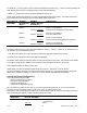
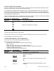
Read Rate:
“INP.2=0” Slow
“INP.2=1” Fast
Input Voltage:
“INP.3=0”
Unipolar
“INP.3=1” Bipolar
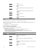
Transmitter Type:
“INP.4=0”
No Transmitter
“INP.4=1” Not used
“INP.4=2” Not used
“INP.4=3” Not used
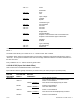
Bridge Mode:
“INP.5=0”
Normal Operation
“INP.5=1” Setpoint 1 value would be lower overload limit and
Setpoint 2 value would be upper overload limit.
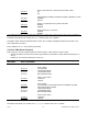
“INP.6=0” Disabled
“INP.6=1” Enabled
Type of Reading:
“INP.7=0” Non Ratiometric
“INP.7=1” Ratiometric
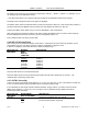
* The ‘MIN’ button allows you to sequence through INPUT 1, INPUT 2, INPUT 3, INPUT 4, INPUT 5, INPUT 6, and
INPUT 7.
The ‘MAX’ button allows you to select the “0” or “1” state for each “INP” condition.
The ‘MENU’ button stores the selected values for all “IN CNF” condition(s) changed and advances the meter to
“IN.SC.OF”. Do not press the ‘MENU’ button after each change within the submenu or the meter will advance to
the next menu item.
Every underlined “0” or “1” state is the factory preset value.
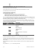
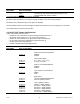
9.2.5 IN.SC.OF (Input Scale And Offset)
Refer to Section 8 for a detailed discussion of this feature.
Input scale and offset is typically used when you want to scale your meter (using two input data points):
MENU
BUTTON
MAIN MENU
MIN/MAX *
BUTTON SUB
MENU 1
MIN/MAX/MENU **
BUTTON
SUB MENU 2
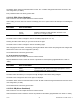
DESCRIPTION
INPUT SCALE OFFSET
Input scale and offset in 2-Coordinate Format
INPUT 1 Item #1 of Coordinate #1.
000000. (“000000.”)
Enter the first value displayed by the meter.
READ 1 Item #2 of Coordinate #1.
000000. (“000000.”)
Enter first desired value.
INPUT 2 Item #1 of Coordinate #2.
000000. (“100000.”) Enter the second value displayed by the meter.
“IN.SC.OF”:
READ 2 Item #2 of Coordinate #2.
CF 67 37 M1291/N/0403 11279ML-02 Rev. A