
Instruction Manual
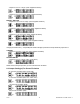
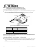
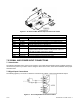
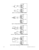
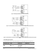
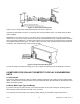

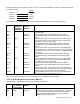
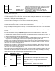

Figure 7-6 Bridge Input With External Sensor Excitation
Figure 7-7 Potentiometer Connections with Internal Power Supply & Ratio Measurement
Figure 7-8 Potentiometer Connections with External Power Supply & Ratio Measurement (Remove jumper
S2-T)
7.3 AC Wiring Connection
The orange (power) connector must be wired according to the following table (also refer to Figure 7-9).
USA WIRING CODE
EUROPE WIRING
CODE
CONNECTION
PIN # ON ORANGE
CONNECTOR
Black Brown ~AC LINE (L) 1
White Blue ~AC Neutral(N) 2
Green Green/Yellow ~AC Protective
Earth Ground 3
CF 67 20 M1291/N/0403 11279ML-02 Rev. A