
Instruction Manual
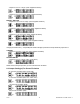
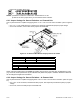
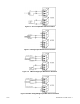
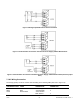
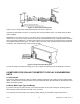
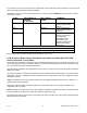

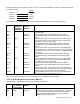
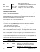

Figure 6.3. dc-Powered Main Board Jumper Positions S3 and S4
S1 On dc-powered units, side power board
S1A Installed For 1.25 to 12 Vdc excitation at 120 mA
S1B Installed For 24 Vdc excitation at 35 mA
S3, S4, S5 On dc-powered unit, main board
S3A Installed To store data and setup parameters in nonvolatile memory
S3B Omit See note in previous section 6.4.1
S3C Installed Unlocks lockout menu (L1 through L4)
S3D Installed Unlocks Front pushbuttons
S4A Installed Along with the S1 jumper to program the excitation output.
Adjust excitation with R34 surface mount pot from 1.25 to 12
volts, with an output current up to 120 mA.
S4A Removed For 24 Vdc excitation. (S4A located in storage position).
S5A Installed To enable the RESET front panel pushbutton.
S5A Removed To secure against unauthorized meter reset.
7.0 SIGNAL AND POWER INPUT CONNECTIONS
7.1 Introduction
The following describes how to connect your sensors to your meter with and without sensor excitation and how to
connect the AC power to your meter. Prior to wiring the sensor to the meter, check with a multimeter that a proper
excitation exists.
7.2 Signal Input Connections
The following figures (7-1 through 7-5) show the connections for voltage, current and potentiometer inputs:
Figure 7-1. Current Input Without Sensor Excitation
CF 67 18 M1291/N/0403 11279ML-02 Rev. A