
Instruction Manual
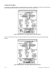
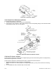
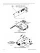
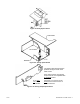

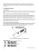

Figures 5-5 through 5-13 show the layout of the seven (7) printed circuit boards with respective jumper blocks,
where applicable, used in the meter. Figures 5-7 through 5-13 show the optional boards.
Figure 5-5. Signal Input Board
Figure 5-6. AC-Powered Main Board
Figure 5-7. DC-Powered Main Board
CF 67 11 M1291/N/0403 11279ML-02 Rev. A