
Instruction Manual
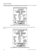
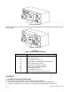
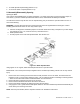
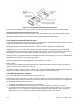
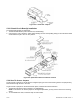
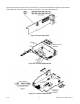

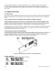

Figure 4-3 Rear View
Figure 4-4 shows the rear of the meter with the optional BCD output board and a serial communications output
board installed.
Figure 4-4. Rear View
TABLE 4-1
REAR CONNECTOR DESCRIPTIONS
CONNECTOR# DESCRIPTION
P1 AC Power Connector
P2 External I/O Connector
P3 Input Connector, –E, +R, –R
J4 Optional RS-232 or RS-485 Phone Jack Connector
P5 Optional Analog Out Connector
P6 Optional Form-C Relay #1 Connector
P7 Optional Form-C Relay #2 Connector
P8 Optional BCD Connector
P9 Input Connector, +E, +S, –S
P18 Optional Form-C Relay #3 and #4 Connector
5.0 SETUP
5.1 Conditions Requiring Disassembly
You may need to remove the sleeve or open the meter for several reasons:
1. To inspect the rating label on the case (not the same label as on the sleeve) (Section 5.2.1).
2. To check or change the 115 V ac or 230 V ac or main board jumpers (Sections 5.2.2 and 5.2.4).
CF 67 7 M1291/N/0403 11279ML-02 Rev. A