DFI INFINITY STRAIN METER/CONTROLLER USER’S GUIDE www.cooperinstruments.
CONTENTS NOTES, WARNINGS AND CAUTIONS .......................................................................................1 1.0 INTRODUCTION ....................................................................................................................1 1.1 Description ...................................................................................................................................... 1 1.2 Features ....................................................................................
9.2.2 RDG.CNF (READING CONFIGURATION).............................................................................. 34 9.2.3 RDG SC (Reading Scale) AND RDG OF (Reading Offset)................................................... 35 9.2.4 IN CNF (Input Configuration)................................................................................................. 36 9.2.5 IN.SC.OF (Input Scale And Offset)........................................................................................37 9.2.
13.8 Bringing Out The BCD Overflow Line ....................................................................................... 60 13.9 3 Digit At A Time Multiplex......................................................................................................... 60 13.10 6 Digit At A Time Card Address............................................................................................... 60 13.11 Select Data Polarity: Jumper S8 ...................................................................
18.3 Potentiometer Input .................................................................................................................... 70 18.4 General......................................................................................................................................... 70 19.0 FACTORY PRESET VALUES............................................................................................73 20.0 RECORD YOUR SETUP VALUES ..............................................................
NOTES, WARNINGS AND CAUTIONS Information that is especially important to note is identified by these labels: • NOTE • WARNING • CAUTION • IMPORTANT NOTE: provides you with information that is important to successfully set up and use the Programmable digital meter. CAUTION or WARNING: tells you about the risk of electric shock. CAUTION, WARNING or IMPORTANT: tells you of circumstances or practices that can affect the meter’s functionality and must refer to accompanying documents. 1.0 INTRODUCTION 1.
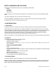
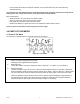
INF-1 INF-2 INF-3 INF-4 INF-5 INF-6 INF-7 INF-12 INF-16 ANALOG OUTPUT CARD W/ 4-20 MA/0-10V OUTPUT RS-232 CARD DUAL RELAY CARD BCD ISOLATED PARALLEL OUTPUT 10-32 Vdc POWER IO CAL RS-485 CARD 4 RELAY BOARD BUMPER BAND 2.0 UNPACKING Remove the Packing List and verify that all equipment has been received. If there are any questions about the shipment, please call the Cooper Instruments & Systems Customer Service Department at 1-800-344-3921 or 540349-4746.
1 Rear Protective Cover with Screw 1 20-Socket Ribbon Connector (P2 Connector) 2 Panel-Mounting Gaskets (1 Spare) 1 1 Strain Gauge Owner’s Guide Quick Start Manual Other items may also be in the box depending on the options ordered. Refer to specific options described previously. 3.0 SAFETY CONSIDERATIONS This device is marked with the international caution symbol.
• Unit mounting should allow for adequate ventilation to ensure instrument does not exceed operating temperature rating. Use electrical wires with adequate size to handle mechanical strain and power requirements. Install without exposing bare wire outside the connector to minimize electrical shock hazards. EMC Considerations • Whenever EMC is an issue, always use shielded cables. • Never run signal and power wires in the same conduit. • Use signal wire connections with twisted-pair cables.
4 S /MAX BUTTON During run mode, pressing this button displays the “HI RDG” (peak reading) value that has occurred up to the moment the ‘MAX’ button is pressed. This peak reading flashes, to distinguish its value from the current readings. Since this is a dynamic peak reading, the value will change if the value increases while reviewing it. To return to display of the current readings without resetting the peak-value memory to zero (0), press the ‘MAX’ button once again.
4.2 Rear Of The Meter The following is a brief description of each part of the rear of the meter. The label on the top of the mounting sleeve (not the case) identifies the location of the connectors found at the rear of the meter. Figure 4-2A. AC Power - Connector Label for Rear Connectors Figure 4-3 shows the rear of the meter with the optional relay output board and a serial communications board installed. Figure 4-2B. DC Power - Connector Label for Rear Connectors CF 67 6 M1291/N/0403 11279ML-02 Rev.
Figure 4-3 Rear View Figure 4-4 shows the rear of the meter with the optional BCD output board and a serial communications output board installed. Figure 4-4.
3. To install optional output board(s) (Section 5.2.3). 4. To mount the meter in a panel (Section 5.2.5). 5.2 Assembly/Disassembly Opening Opening the Meter Your meter is fully assembled, but not wired. See Section 7 for wiring connection for power and sensor inputs. In most cases, if you have ordered optional boards with the meter, these boards will already be installed.
Figure 5-2. Board Assembly Removing/Installing Detail The meter is now disassembled to the point where you can check and configure jumpers and install boards. Reinserting the Main Board Assembly into the Case Reinsert the main board into the case once jumper s and optional boards have been configured and installed. Spread the side-panel detents of the case and carefully slide the main board all the way in. 5.2.
Figure 5-3. Transformer Jumpers 5.2.3 Printed Circuit Board(s) Installation To install optional printed circuit board(s): 1. “Reveal the Main Board” (refer to Section 5.2, Disassembly). 2. Using Figure 5-4 as a reference, insert option board(s) into the corresponding slot(s) on the main board. Each circuit board is keyed to fit in it’s own position. Figure 5-4. Optional Printed Circuit Board Locations 5.2.
Figures 5-5 through 5-13 show the layout of the seven (7) printed circuit boards with respective jumper blocks, where applicable, used in the meter. Figures 5-7 through 5-13 show the optional boards. Figure 5-5. Signal Input Board Figure 5-6. AC-Powered Main Board Figure 5-7. DC-Powered Main Board CF 67 11 M1291/N/0403 11279ML-02 Rev.
Figure 5-8. Relay Option Board Figure 5-9. 4-Relay Option Board The Analog option board has been updated. The figure shown is the latest version. Some older versions of the analog output cards are not compatible with dc-powered meters. S1-A does not need to be installed. Check the J12 connector on the main board to ensure it has a 10 position connector. Figure 5-10. Analog Output Option Board CF 67 12 M1291/N/0403 11279ML-02 Rev.
The RS-232 option board has been updated. The figure shown is the latest version. Some older versions of the RS-232 cards are not compatible with dcpowered meters. Check the J11 connector on the main board to ensure it has a 12 position connector. Figure 5-11. RS-232 Option Board The RS-485 option board has been updated. The figure shown is an older version, the newer version is the same figure as the RS-232 option card shown above. Figure 5-12. RS-485 Option Board Figure 5-13. BCD Option Board 5.2.
2. You have configured all jumpers – those on the main board as well as those on any optional boards. See Section 5.2.2 for main board jumper configuration and the appropriate sections for optional board jumper configuration. 3. You have installed all optional boards and inserted the main board assembly back into the case. See Section 5.2.3. 4. You have wired P1, the AC power connector, and P2 the input output control connector; connectors are not installed in the meter, but are ready to be installed.
The meter display should light, and pass through “RESET 2” to run or display mode. If the meter flashes an overscale or overload message, press the ‘MENU’ button to advance to the configuration mode. Do not be concerned about overloads (the +S input can stand 120 V continuously and current inputs can handle ten times rated current). 6.0 JUMPER POSITIONS 6.
Jumpers for 0 to 10 V range: (meter supplied excitation) Jumpers for 0 to 100 V range: (meter supplied excitation) BRIDGE – BIPOLAR Jumpers for –50 to +50 mV range: (meter supplied excitation) Jumpers for –500 to +500 mV range: (meter supplied excitation) Jumpers for –5 to +5 V range: (meter supplied excitation) Jumpers for –50 to +50 V range: (meter supplied excitation) Voltage (Non-Ratiometric) – Unipolar/Bipolar similar to Bridge inputs above except substitute jumper M for L.
1.6 mA meter excitation (S2P, S2V) NOTES: 1) Maximum excitation for “Ratiometric” measurement is 10 Vdc. 2) Remove the “S2T” jumper when you use external sensor excitation. 6.4.1 Jumper Settings for Sensor Excitation –ac Powered Unit Your ac-powered meter is capable of supplying either 1.5 to 11 Vdc or 24 Vdc sensor excitation. (refer to Figure 62). • For 1.5 to 11 Vdc, install S4A and C jumpers, then adjust the potentiometer (R39) for proper voltage.
Figure 6.3. dc-Powered Main Board Jumper Positions S3 and S4 S1 On dc-powered units, side power board S1A Installed For 1.25 to 12 Vdc excitation at 120 mA S1B Installed For 24 Vdc excitation at 35 mA S3, S4, S5 On dc-powered unit, main board S3A Installed To store data and setup parameters in nonvolatile memory S3B Omit See note in previous section 6.4.
Figure 7-2. Current Input With Sensor Excitation Figure 7-3 Voltage Input Without Sensor Excitation Figure 7-4 3-Wire Voltage Input With Sensor Excitation Figure 7-5 4-Wire Voltage/Bridge Input With Sensor Excitation CF 67 19 M1291/N/0403 11279ML-02 Rev.
Figure 7-6 Bridge Input With External Sensor Excitation Figure 7-7 Potentiometer Connections with Internal Power Supply & Ratio Measurement Figure 7-8 Potentiometer Connections with External Power Supply & Ratio Measurement (Remove jumper S2-T) 7.3 AC Wiring Connection The orange (power) connector must be wired according to the following table (also refer to Figure 7-9).
Figure 7-9. AC Connector Wiring at P1 Connect your AC meter power as described above and as shown in Figure 7-9. CAUTION: As mentioned in Section 5.2.2, the meter has no power ON/OFF switch. The meter will be ON when power is applied. WARNING: Do not connect ac power to your meter until you have completed all input and output connections. Failure to do so may result in injury! This device must only be installed electrically by a specially trained electrician with corresponding qualifications.
If you received your meter and it is has been configured for an input other than what you require, you must proceed with the following steps before rescaling the display: WARNING: You must set your jumper positions at the S1 and S2 positions BEFORE proceeding. Refer to Section 6 for jumper positions. PRESS THEN PRESS (TO CHANGE IF REQUIRED) UNTIL DISPLAY SHOWS COMMENTS ‘MENU’ ‘“INPUT” ‘MIN’ “BRIDGE” ‘MENU’ “BRIDGE” Press the ‘MENU’ button until the display shows “INPUT”.
8.3.1 SETTING INPUT CONFIGURATION (IN CNF) PRESS THEN PRESS (TO CHANGE PRESS IF REQUIRED) UNTIL DISPLAY SHOWS COMMENTS ‘MENU’ “IN CNF” Press the ‘MENU’ button until the display shows “IN CNF”. ‘MIN’ “INP.3=0” ‘MAX’ “INP.3=0” Press the ‘MIN’ button until the display shows “INP.3=0” or “INP.3=1”. Press the ‘MAX’ button to select “INP.3=0”- Unipolar input for current, voltage and potentiometer inputs. OR ‘MAX’ “INP.3=1” ‘MIN’ “INP.6=0” OR “INP.6=1” ‘MAX’ “INP.
Record your “INPUT1” and “READ 1” numbers, and your “INPUT2” and “READ 2” numbers, record them below and proceed as follows: Example INPUT1= 000003. READ 1 = 000000. INPUT2 = 100018. READ 2 = 068000. For the purpose of this example, we will use the numbers described above for the following procedure: PRESS THEN PRESS (TO CHANGE IF REQUIRED) UNTIL DISPLAY SHOWS COMMENTS ‘MENU’ “IN.SC.OF” ‘MIN’ ‘MIN’ “INPUT1” “XXXXXX” Press the ‘MENU’ button until the display shows “IN.SC.OF” Input Scale and Offset.
decimal point location within the “F’s” Press the ‘MENU’ button to store your decimal point selection and the meter will momentarily display “STORED” only if you have made a change and then “CNT BY”. ‘RESET’ ‘RESET’ “RESET2” then the Press the ‘RESET’ button two times. The display will Measured Value momentarily show “RESET2” and then will display the currently measured values. Your meter is now calibrated.
‘RESET’ ‘RESET’ “RESET2” then The Measured Value Press the ‘RESET’ the button two times. display will momentarily show “RESET2” and then will display the currently measured values. NOTE: If after zeroing the display with RDF OF, the reading again drifts from zero, the required offset value is the sum of the current RDG OF value and the current converted offset value. The examples below illustrate the calculation of required offset values when using an independent decimal.
PRESS THEN PRESS (TO CHANGE IF REQUIRED) ‘MENU’ UNTIL DISPLAY SHOWS COMMENTS Press the ‘MENU’ button until the display shows “IN.SC.OF” Input Scale and Offset. ‘MIN’ “INPUT1” Press the ‘MIN’ button and the display will show “INPUT1”. ‘MIN’ “XXXXXX” Press the ‘MIN’ button and the display will show some 6-digit number. ‘MENU’ “IN.SC.OF” Press the ‘MENU’ button until the display shows “IN.SC.OF” Input Scale and Offset. ‘MIN’ “INPUT1” Press the ‘MIN’ button and the display will show “INPUT1”.
These calculated scale factors are the numbers that your meter would display if you connected a signal source. You must complete the procedure for preparing your meter for scaling as described in Section 8.4.1. Failure to complete this procedure will result in erroneous readings.
‘MAX’ ‘MIN’ “000000.” Using the ‘MAX’ button to change the value of the flashing digit and the ‘MIN’ button to scroll to the next digit to the right, enter the engineering value that you want your “INPUT 1” number to display on the meter. ‘MENU’ “INPUT2” Press the ‘MENU’ button and the display will show “INPUT2”. ‘MIN’ “XXXXXX” Press the ‘MIN’ button and the display will show some 6-digit number. ‘MAX’ ‘MIN’ “050000.
enter “–00020” in Reading Offset (“RDG OF”) and if your zero input shows a negative “–20” you would enter a positive 000020 in Reading Offset (“RDG OF”). PRESS ‘MIN’ THEN PRESS (TO CHANGE IF REQUIRED) ‘MAX’ ‘MENU’ ‘RESET’ UNTIL DISPLAY SHOWS “XXXXXX” “STORED” ‘RESET’ “RESET2” then the Measured Value COMMENTS Use the ‘MIN’ button to move to each digit and the ‘MAX’ button to change the flashing digits value and enter your zero offset number.
‘MENU’ ‘RESET’ ‘RESET’ “STORED” the “IN CNF” “RESET2” then the Measured Value Press the ‘MENU’ then button to store your selection. The display will momentarily show “STORED” then “IN CNF”. Press the ‘RESET’ then the button two times. The display will momentarily show “RESET2” and then will display the currently measured values.
MENU BUTTON MAIN MENU “L1 CNF”: MIN/MAX* BUTTON SUB MENU CONDITION LOCKOUT CONFIGURATION #1 “L1C.1=0” Setpoint 1 change unlocked. “L1C.1=1” Setpoint 1 change locked out. “L1C.2=0” Setpoint 2 change unlocked. “L1C.2=1” Setpoint 2 change locked out. “L1C.3=0” Setpoint 3 (Alarm 1) change unlocked. “L1C.3=1” Setpoint 3 (Alarm 1) change locked out. “L1C.4=0” Setpoint #4 (Alarm 2) change unlocked. “L1C.4=1” Setpoint #4 (Alarm 2) change locked out. “L1C.5=0” Valley-value (LO RDG) display is permitted. “L1C.
“L2C.8=0” FIL CNF (adaptive/fixed filtering and for which output(s)) can be chosen. “L2C.8=1” FIL CNF (adaptive/fixed filtering and for which output(s)) cannot be chosen. * The ‘MIN’ button allows you to sequence through L2C.1, L2C.2, L2C.3, L2C.4, L2C.5, L2C.6, L2C.7, and L2C.8. The ‘MAX’ button allows you to select the “0” or “1” state for each “L2C” condition. The ‘MENU’ button stores the selected values for all “L2C” condition(s) changed and advances the meter to “L3 CNF”.
MENU BUTTON MAIN MENU “L4 CNF”: MIN/MAX* BUTTON SUB MENU DESCRIPTION LOCKOUT CONFIGURATION #4 “L4C.1=0” BAUD (communication rate) can be chosen. “L4C.1=1” BAUD (communication rate) cannot be accessed. “L4C.2=0” SER.CNF (parity/stop-bit length) is selectable. “L4C.2=1” SER.CNF (parity/stop-bit length) is not selectable. “L4C.3=0” ADDRES (meter address # on a multipoint bus) can be changed. “L4C.3=1” ADDRES (meter address # on a multipoint bus) cannot be accessed. “L4C.
The 2-data-point method allows the user to use two known points to convert from one scale to another. For example, to convert from degrees Fahrenheit to degrees Celsius, enter two (2) known points, such as 32°F = 0°C and 0 F = 17.77°C. The meter will automatically compute scale and offset and display the correct value. MENU BUTTON MAIN MENU “RDG.CNF”: MIN/MAX/ MENU* BUTTON SUB MENU DESCRIPTION “RDG.1=0” “RDG.1=1” READING CONFIGURATION Reading Scale & Offset: Direct Format 2-Coordinate format “RDG.
For “RDG OF”, you may choose to enter a reference temperature offset here (e.g., “-100.00”) so that the display will read deviation of the input from the boiling point (or some other temperature). If “RDG.1 = 1” were chosen, then you go automatically into “RD.SC.OF”. NOTE: Direct reading offset “RDG OF” now has programmable decimal point position. This makes the decimal point independent of the display decimal point and allows larger offset values.
“INP.1=1” 50 Hz “INP.2=0” “INP.2=1” Read Rate: Slow Fast “INP.3=0” “INP.3=1” Input Voltage: Unipolar Bipolar “INP.4=0” “INP.4=1” “INP.4=2” “INP.4=3” Transmitter Type: No Transmitter Not used Not used Not used “INP.5=0” “INP.5=1” Bridge Mode: Normal Operation Setpoint 1 value would be lower overload limit and Setpoint 2 value would be upper overload limit. “INP.6=0” “INP.6=1” Disabled Enabled Type of Reading: “INP.7=0” Non Ratiometric “INP.
000000. (“100000.”) Enter second desired value. * The ‘MIN’ button allows you to sequence through “INPUT 1”, “READ 1”, “INPUT 2”, and “READ 2” headings. The ‘MAX’ button sends you to the value that corresponds to “INPUT 1”, “READ 1”, “INPUT 2”, or “READ 2” so you can change it (go to the SUB MENU 2 item). ** The ‘MIN’ button allows you to sequence through the digits of the applicable number being changed. The ‘MAX’ button changes the value of the digit to be displayed.
“010” “020” “050” “100” *Press the ‘MIN’ button to show “001”, “002”, “005”, “010”, “020”, “050”, or “100”. Press the ‘MAX’ button to select one of the above. Press the ‘MENU’ button to store the Count By number and the meter will advance to “FIL.CNF”. The underlined item is the factory preset value. 9.2.8 FIL.CNF (Filter Configuration) Filter configuration is used to select: • Adaptive Bandwidth Control (ABC) filtering or moving average filter [FIL.
9.2.9 FIL TI (Filter Time Constant) Filter time constant is used to determine the number of readings the meter will average before displaying an input value. The choices are 001, 002, 004, 008, 016, 032, 064, or 128.
“SPC.3=1” Filtered “SPC.4=0” “SPC.4=1” Setpoint 2 Active zone: Above Below “SPC.5=0” “SPC.5=1” Setpoint 2 open-collector or relay output Active ON or OFF: On Off “SPC.6=0” “SPC.6=1” Filtered/unfiltered reading compared with Setpoint 2 value: Unfiltered Filtered “SPC.7=0” “SPC.7=1” Setpoints 1 & 2 action: Enabled Disabled Setpoint 1 & 2 LEDs action: “SPC.8=0” Enabled “SPC.8=1” Disabled * The ‘MIN’ button allows you to sequence through SPC.1, SPC.2, SPC.3, SPC.4, SPC.5, SPC.6, SPC.7 and SPC.8.
“ALC.5=0” “ALC.5=1” Alarm 2 open-collector or relay output Active ON or OFF: On Off “ALC.6=0” “ALC.6=1” Filtered/unfiltered reading compared with Alarm 2 (Setpoint 4) value: Unfiltered Filtered “ALC.7=0” “ALC.7=1” Alarms 1 & 2 (Setpoints 3 & 4) action and LEDs: Enabled Disabled Alarm reset at P2-11 connector: Disabled “ALC.8=0” “ALC.8=1” Enabled * The ‘MIN’ button allows you to sequence through ALC.1, ALC.2, ALC.3, ALC.4, ALC.5, ALC.6, ALC.7 and ALC.8.
The ‘MENU’ button stores the selected values for each “ALF” condition changed and advances the meter to the next configuration (“AL RDG”). Every underlined item is the factory preset value. 9.2.13 AL RDG (Alarm Readings) Refer to Section 10 for an in-depth discussion of these features. Alarm reading is used to select the number of readings (from 01 to 15) the meter must make prior to activating the alarms.
MENU BUTTON MAIN MENU “AL DB”: MIN/MAX/MENU * BUTTON SUB MENU DESCRIPTION ALARMS 1 & 2 DEADBAND “0000” Hysteresis for (with system decimal points) Alarms 1 & 2 (“0020”) (Programmable from “0000” to “9999”) * Press the ‘MIN’ button to show the value on the display. The ‘MIN’ button also allows you to sequence through the digits of the number being changed. The ‘MAX’ button changes the value of the digit to be displayed.
The ‘MAX’ button allows you to select the “0”, “1”, “2”, “3”, “4” or “5” state for each “OUT” condition. The ‘MENU’ button stores the selected values for each “OUT” condition changed and advances the meter to the next configuration (“OT.SC.OF”). Every underlined item is the factory preset value. 9.2.17 OT.SC.OF (Output Scale And Offset) Output scale and offset is used to calibrate your optional analog output to correspond to the engineering units you desire.
Press the ‘MAX’ button to select one of the above. Press the ‘MENU’ button to store the changes and the meter advances to the next configuration (“SERCNF”). The underlined item is the factory preset value. 9.2.19 SERCNF (Serial Communication Configuration) Serial communication configuration is used to select: • no parity, odd parity, or even parity for communications [SER.1] • 1 stop bit or 2 stop bits [SER.
Data format allows you to select: • whether to transmit Alarm 1 or 2 status character [DAT.1] • whether to transmit peak and valley status character [DAT.2] • whether or not the data transmitted is filtered or unfiltered [DAT.3 & DAT.4] • whether or not to transmit the peak and valley readings [DAT.5 & DAT.6] • the type of separator [DAT.7] • whether or not to transmit the unit of measure [DAT.8] MENU BUTTON MAIN MENU “DAT FT”: MIN/MAX/MENU * BUTTON SUB MENU DESCRIPTION “DAT.1=0” “DAT.
• • • • • multipoint or point-to-point mode [BUS.4] (if in point-to-point mode) select whether to communicate continuously or on command [BUS.5] whether a message character is used in handshake or continuous mode [BUS.6] whether or not you have installed the RS-485 board [BUS.7] whether or not to enable the external print command at P2-11. MENU BUTTON MAIN MENU “BUS FT”: MIN/MAX/MENU * BUTTON SUB MENU DESCRIPTION BUS FORMAT “BUS.1=0” “BUS.1=1” Check sum with reading: Excluded Included “BUS.2=0” “BUS.
MENU BUTTON MAIN MENU “SERCNT”: MIN/MAX/MENU * BUTTON SUB MENU DESCRIPTION SERIAL COUNT This specifies the number of readings between data transmissions: “00000” (“00001”) “00001” to “59999” * Press the ‘MIN’ button to show the value on the display. The ‘MIN’ button also allows you to change the position of the digit being changed. The ‘MAX’ button changes the value of the digit to be displayed. Press the ‘MENU’ button to store the changes and advances the meter to “RESET 2” and returns to the run mode.
10.1 Features Overview 1. 2. 3. 4. 5. 6. 7. 8. 9. 10. 11. Four full-range levels with many menu programmable features. Independent operation or ganged action (including guard-band assignments). Active above or below level, outside or inside band. SP1 and SP2 have configurable hysteresis, 50% on either side of setpoint. SP3 and SP4 have configurable hysteresis, 100% on inactive side. SP3 and SP4 is configurable for latching action.
2. Press the ‘MENU’ button to see “L1 CNF” and then press the ‘MIN’ button to view “L1C.1=0” if “SP 1” is unlocked. If “L1C.1=1”, change to equal “0” by pressing the ‘MAX’ button. 3. Press the ‘MIN’ button again to advance to “L1C.2” and set equal to “0” to unlock “SP 2”. 4. Repeat for “L1C.3=0” and “L1C.4=0” to access “SP 3” and “SP 4”. 5. Press the ‘MENU’ button to save these choices and advance to “L2 CNF”. Skip over “L2 CNF” by pressing the ‘MENU’ button and advance to “L3 CNF”. 6.
Figure 10-4. High Deviation for both Active Above and Active Below Figure 10-5. Low Deviation for both Active Above and Active Below Figure 10-6. Band Deviation for both Active Above and Active Below 10.5 Selecting AL CNF Alarm Configuration Features These bits offer the same selections for “SP 3” and “SP 4” as “SP CNF” did for “SP 1” and “SP 2”, except for the last bit, which controls “SP 3” and “SP 4” LATCH reset. 1.“ALC.1=0” makes Alarm 1 (Setpoint 3) active above the Setpoint value. “ALC.
Figure 10-7. AL CNF Hysteresis 2.“ALC.2=0” turns the Alarm 1 (Setpoint 3) open-collector output ON when Setpoint 3 is active. “ALC.2=1” turns it OFF. 3. “ALC.3=0” compares the Alarm 1 (Setpoint 3) level to the UNFILTERED measurements. “ALC.3=1” compares the Alarm 1 (Setpoint 3) level to the FILTERED measurements. 4.“ALC.4=0” makes Alarm 2 (Setpoint 4) active ABOVE the Setpoint value. “ALC.4=1” makes Alarm 2 (Setpoint 4) active BELOW the Setpoint value.
3.“ALF.3=0” makes “SP 4” INDEPENDENT, with a level equal to the value inserted for “SP 4”. “ALF.3=1” assigns “SP 4” to “SP 2”, placing it ABOVE “SP 2” by the amount entered for “SP 4”. “ALF.3=2” places “SP 4” BELOW “SP 2” by the amount entered for“SP 4”. “ALF.3=3” places “SP 4” ON BOTH SIDES OF “SP 2” by the amount entered for “SP 4”. 4.“ALF.4=0” makes Alarm 2 (Setpoint 4) a NON-LATCHING Alarm. “ALF.4=1” makes Alarm 2 (Setpoint 4) LATCHING.
10.11 Entering Setpoint Levels (In Run Mode) When you have completed selecting the setpoint(s) (and other features), the last press of the ‘MENU’ button stores any changes and the meter will automatically return to the run mode (the display will momentarily display “RESET2”). The stored values are placed into operation, and the meter proceeds with normal measurements. Now you can view and reset all four setpoint levels. 1. Press the ‘SETPTS’ button.
Your meter converts display readings into an independently-scaled and-offset isolated voltage and/or current analog output. Isolation is accomplished via opto-isolators on the board. Your meter has the capability of transmitting SIMULTANEOUS voltage and current outputs although when this is done, the current analog output is not as accurate. 12.1 Features Overview 1. Precise analog levels are generated from digital code using a proprietary ASIC chip. 2.
3. Store this value by pressing the ‘MENU’ button and then advance to “READ2”. Use the ‘MIN’ and ‘MAX’ buttons to enter a large display value, for example, “123.456”, for the display that you want the analog output at full scale. 4. Store this value by pressing the ‘MENU’ button and then advance to “OUTPT2”. Use the ‘MIN’ and ‘MAX’ buttons to enter the desired output for the display value in step 3. For example, enter “20.0000” for calibrated current or “10.0000” for calibrated voltage. 5.
12.6 Filter Configuration FIL.CNF Value To Be Transmitted On Analog Output 1. Press the ‘MENU’ button until the display shows “FIL.CNF”. 2. Press the ‘MAX’ button until the display shows “FIL.3=0”, “FIL.3=1”, “FIL.3=2”, or “FIL.3=3”. 3. “FIL.3=0” Transmits the unfiltered value of your signal input. “FIL.3=1” Transmits the filtered value of your signal input. “FIL.3=2” Transmits the recorded PEAK (“HI RDG”) value(s). “FIL.3=3” Transmits the recorded VALLEY (“LO RDG”) value(s). 4.
Figure 13-2 shows the board connections and pin designators. The locations of the jumpers are also shown. Figure 13-2. BCD Option Board 13.
13.5 Selecting The Source Of BCD Data: “OUT .CNF” If “L3C.7=0” has been selected to unlock the Output Configuration byte, set “OUT.3=1” to send data to this BCD board. “OUT.4=0” selects that data as the DISPLAYED (current) measurement value. “OUT.4=1” sends the PEAK (HI) value to the BCD. Save your selection by pressing the ‘MENU’ button. 13.6 Hold Control P8-U17 is the HOLD line, referenced to the same ground as the BCD outputs (on P8-L15 and P8-L3).
Figure 13-3. Address Programming Chart for 4-line Address NOTE: “X” in chart indicates jumper that must be installed. EXAMPLE: For a positive true address of 03, install jumpers S5-G and S5-E. If any of these jumpers are removed, the corresponding line must go HIGH or OPEN to assist the card enable; if all four jumpers are missing, for example, the card outputs are enabled ONLY when all four lines are HIGH or OPEN, a ground on any of the four input lines causes the outputs to go to the high impedance state.
1-ampere Form-C electro-mechanical relays for 4 Relay Option). Each relay can accommodate a single setpoint. 200 W, 2500pf snubbers are provided for each normally open contact. These options may not be used with parallel BCD Board Option. Figure 14-1 and 14-2 shows the board connections and jumper locations. Figure 14-1. Relay Option Board With S1 Jumper Positions and Connection Diagram. Table 14.
B,D A, C B,D B,D A,C B,D Assigns SP2 to Relay 2 (P7) Assigns SP3 to Relay 1 (P6) Assigns SP4 to Relay 4 (P18) Assigns SP1 to Relay 3 (P18) Assigns SP2 to Relay 4 (P18) Assigns SP3 to Relay 1 (P6) Assigns SP4 to Relay 2 (P7) Assigns SP1 to Relay 1 (P6) Assigns SP2 to Relay 4 (P18) Assigns SP3 to Relay 3 (P18) Assigns SP4 to Relay 2 (P7) 14.2 Wiring/Connections WARNING: Do not connect ac power meter until you have completed all input and output connections.
5 6 Common 4 NC4 (Normally Closed) 15.0 RS-232 OR RS-485 OPTION BOARD 15.1 Features Overview The Isolated Serial RS-232 Communications Board provides an isolated digital communications channel between a single meter and another meter or device, or between a single meter and a computer. The Isolated Serial RS-485 Communications Board adheres to the IEC standard, providing an intelligent device – but can actually address up to 199 devices. 1.
Figure 15-2a. Older RS-232 Option Board and Pin Designations Figure 15-2b. Older RS-485 Option Board and Pin Designations 15.2 Front-Panel Pushbutton Configuration Setup configuration can be accomplished via the front panel buttons or via your computer if you use the configuration setup program. If you are going to use a computer, your choices include “AUTO SET” or “MANUAL SET” for establishing communication with your meter.
16.1 Tare (PIN 1) Tare is available when pin P2-1 and P2-4 are connected to a momentary contact switch. This feature allows you to automatically zero your meter when the switch is activated. 16.2 Peak (PIN 2) When this is connected to P2-4 by an external switch, the meter displays the stored PEAK (“HI RDG”) value rather than the current reading. The display flashes to distinguish this value. 16.
16.11 Print Command And/Or Reset Of Alarms (PIN 11) Grounding this pin to P2-7 when “BUS.8=1” has been programmed will initiate a meter printout via serial communications in the format previously selected. If “ALC.8=1” it causes the alarm latches to reset. 16.12 Nonstandard RX (PIN 12) And Nonstandard TX (PIN 13) These two pins allow digital communications with the meter using 5 V CMOS logic levels and RS-232 protocols and format.
17.1 Error Mode Messages 17.1.1 Flashing 999999 (Numerical Overflow) The maximum number of counts in the display cannot exceed –99999 or 999999. If, by moving the ACTIVE decimal point one or more places to the left, you cause the display to move beyond the maximum number of counts it is capable of showing (for example, 12345.0 to 12345.00), the display will indicate the overflow by flashing “999999”. 17.1.
17.2 Troubleshooting Guide 99999 POSSIBLE CAUSE: Active decimal point change driving the display into numerical overload. TO CORRECT: Press the ‘MAX’ button to reset the entire display to all zeros, then enter a revised number into the submenu item that caused the overflow. ERR 01 POSSIBLE CAUSE: Active decimal (“RDG.2=0”) has been selected and/or DEC PT (decimal point) position has been moved one or more places to the left driving the programmed offset value into numerical overflow.
TO CORRECT: Reduce the “CNT BY” count by value to 001. If you have an active decimal point selected, move the decimal point one or more positions to the right. UOM.OVF POSSIBLE CAUSE: Selection of unit of measure displayed (“RDG.6=0”) moves the display reading one place to the left causing a numerical overflow. TO CORRECT: If you have an active decimal point, move he decimal point position one or more positions to the right.
SPAN TEMPCO: STEP RESPONSE: WARMUP: less than 20 ppm/°C 1 second to 99.9% 55 minutes to rated accuracy It is recommended that the unit be continuously running to insure its accuracy. CONVERSION TECHNIQUE: Dual-slope INTEGRATION TIME: READRATE and DISPLAY UPDATE/Programmable 3 samples/sec: 100 msec 13 samples/sec, 60 Hz: 16.
0.001% of span/volt power supply rejection EXTERNAL FUSE REQUIRED: 115 Vac 230 Vac IEC 127-2/III,125 mA,250V (Time-Leg) or UL Slow Blow, 125mA, 250V IEC 127-2/III,63 mA,250V (Time-Leg) or UL Slow Blow, 63mA, 250V ENVIRONMENTAL OPERATING TEMP RANGE: STORAGE TEMP RANGE: HUMIDITY: FRONT PANEL: 0 to 50 degrees C (32 to 140°F) –40 to 85 degrees C (–40 to 202°F) up to 95% non-condensing at 40°C (104°F) NEMA-4 rated MECHANICAL DIMENSIONS (H x W x D): PANEL CUTOUT (H X W): WEIGHT: MATERIAL: 1.89 x 3.78 x 5.
DURING SETPOINT ADJUST (RUN MODE) OUT OF SELECTED DIGIT RANGE: NOT STORED IN EEPROM: VALUE PUT IN EEPROM: “999999” “NOSTOR” “STORED” 19.0 FACTORY PRESET VALUES JUMPER POSITIONS: ac Powered unit S1: NONE S2: A, F, L, N, T S3: A, C S4: A, C dc Powered unit S1 (dc power board A S1: NONE S2:A F, L, N, T S3: A, C, D S4: A S5: A LOCKOUT CONFIGURATION (VS) L1 CNF L2 CNF L3 CNF L1C.1=0 L2C.1=0 L3C.1=0 L1C.2=0 L2C.2=0 L3C.2=0 L1C.3=0 L2C.3=0 L3C.3=0 L1C.4=0 L2C.4=0 L3C.4=0 L1C.5=0 L2C.5=0 L3C.5=0 L1C.6=0 L2C.
Setpoints 1 & 2 Deadband “SP DB”: 0020 Alarms 1 & 2 Deadband “AL DB”: 0020 Output Configuration “OUT.CNF”: OUT.1=0 OUT.2=1 OUT.3=0 OUT.4=0 OUT.5=1 OUT.6=0 Output Scale and Offset “OT.SC.OF”: READ 1: 000000. OUTPT 1: 04.0000 READ 2: 100000. OUTPT 2: 20.0000 Baud Rate “BAUD”: 09600 Serial Communication Configuration “SERCNF”: SER.1=1 SER.2=0 Address “ADDRES” (for RS-485): 001 Data Format “DAT FT”: DAT.1=0 DAT.2=0 DAT.3=1 DAT.4=0 DAT.5=0 DAT.6=0 DAT.7=0 DAT.8=0 Bus Format “BUS FT”: BUS.1=0 BUS.2=0 BUS.3=1 BUS.
For Pot: __________ Reading Configuration “RDG.CNF”: RDG.1=__ RDG.2=__ RDG.3=__ RDG.4=__ RDG.5=__ RDG.6=__ RDG.7=__ Reading Scale and Reading Offset “RDG SC” and “RDG OF” (Direct Format): Reading Scale “RDG SC”: ___________ Reading Offset “RDG OF”: ___________ Reading Scale & Offset: (2-coordinate Format): INPUT 1= __________ READ 1= __________ INPUT 2= __________ READ 2= __________ Input Configuration “IN CNF”: INP.1=__ INP.2=__ INP.3=__ INP.4=__ INP.5=__ INP.6=__ INP.7=__ Input Scale and Offset “IN.SC.
Address “ADDRES” (for RS-485): ______ Data Format “DAT FT”: DAT.1=__ DAT.2=__ DAT.3=__ DAT.4=__ DAT.5=__ DAT.6=__ DAT.7=__ DAT.8=__ Bus Format “BUS FT”: BUS.1=__ BUS.2=__ BUS.3=__ BUS.4=__ BUS.5=__ BUS.6=__ BUS.7=__ BUS.