
Manual

4
PART 2
HARDWARE
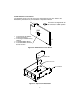
2.1 Physical Characteristics and Mounting
For physical dimensions and installation instructions reference the Quickstart and
Operator’s Manual .
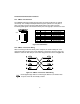
2.2 Rear Panel of Meter with Embedded Ethernet Server
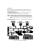
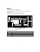
Figure 2.1 Rear Panel View of Meter
with Embedded Ethernet Server
Table 2.1 Rear Panel Annunciators
Network Communication Interface Section:
ETHERNET RJ45 interface for 10BASE-T connection.
RESET Button: Used for power reseting the iServer.
COL LED (Red) Blinking: Indicates network activities (receiving or sending packets).
ON LED (Green) Solid: Indicates good network link.
11
11
1
1
1
1
1
119
P6 P7 P18A P18B
J4
P2
P9
P3
P5
P1
ETHERNET
RESET
COL
ON