
Manual

ON.L INE
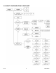
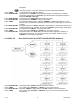
Press ‘RESET/ENTER’ 30) Display flashes "ON.L INE" On line method.
Press ‘▲/MAX’ 31) Scroll between 2 available selections: "ON.L INE" or "MANUAL" for the configuration
option of your choice. If your choice of selection is "MANUAL", skip to Step 40).
Press ‘RESET/ENTER’ 32) Display stops flashing and shows "ON.L INE".
Press ‘RESET/ENTER’ 33) Display shows "INPUt 1" Item #1 of coordinate #1.
Pressing ‘RESET/ENTER’ to sequence through
"INPUt 1", Input 1 ‘s value
"REAd 1", Read 1 ‘s value
"INPUt 2", Input 2 ‘s value
"REAd 2", Read 2 ‘s value
headings for the desired selection to enter new value.
Press ‘RESET/ENTER’ 34) Display shows "xxxxxx" some 6-digit number, represents the value of "INPUt 1" as
taken from live input source measurement for desired value.
Press ‘RESET/ENTER’ 35) Display shows "REAd 1" Item #2 of coordinate #1.
Press ‘RESET/ENTER’ 36) Display shows "xxxxxx" some 6-digit number with first digit flashing, represents the
value of "REAd 1" item #2 of coordinate #1.
Press ‘▲/MAX’ & ‘►/MIN’ 37) Use ‘MAX’ and ‘MIN’ buttons to enter new value of "REAd 1".
Press ‘RESET/ENTER’ 38) Display shows "INPUt 2" Item #1 of coordinate #2. Continue to proceed with the
selection and value entry for "INPUt 1" and "REAd 1" for "INPUt 2" and "REAd 2", (item
#1 and #2 of coordinate #2) similar to steps above.
Press ‘RESET/ENTER’ 39) Display advances to "MP.SC.OF" Multi-Scale & Offset configuration menu. If "REAd 1"
item #2 of coordinate #2 was prompted or modified, the controller will also show "StOREd"
stored message momentarily.
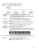
MANUAL
Press ‘RESET/ENTER’ 40) "MANUAL" heading stops flashing.
Press ‘RESET/ENTER’ 41) Display shows "INPUt 1" Item #1 of coordinate #1.
Pressing ‘RESET/ENTER’ to sequence through
"INPUt 1", Input 1 ‘s value
"REAd 1", Read 1 ‘s value
"INPUt 2", Input 2 ‘s value
"REAd 2", Read 2 ‘s value
headings for the desired selection and continue using ‘MAX’ and ‘MIN’ buttons to manually
enter or modify the values as described the below section.
Press ‘RESET/ENTER’ 42) Display shows "xxxxxx" some 6-digit number with first digit flashing, represents the
value of "INPUt 1" item #1 of coordinate #1.
Press ‘▲/MAX’ & ‘►/MIN’ 43) Use ‘MAX’ and ‘MIN’ buttons to enter new value of "INPUt 1" item #1 of coordinate #1.
Press ‘RESET/ENTER’ 44) Display shows "REAd 1". Continue with the sequential items and use ‘MAX’ & ‘MIN’
buttons to select and enter values.
Press ‘RESET/ENTER’ 45) Display advances to "MP.SC.OF" Multi-point Scale & Offset Configuration Menu. If
"REAd 2" item #2 of coordinate #2 was prompted or modified, the controller will also
shows "StOREd" stored message momentarily.
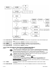
SCALING YOUR METER
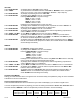
Scaling your meter without a sensor or a signal source connected is easily accomplished by using one of the calculated
scale factors as shown in Table below.
Scaling to Display Engineering Units
These calculated scale factors are the numbers that your meter would display if you connected a signal source.
You must complete the procedure for preparing your meter for Scaling as described in Section 16.4 "IN.SC.OF" INPUT
SCALE & OFFSET, "MANUAL". Failure to complete this procedure will result in erroneous readings.
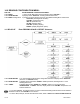
Input Signal Range
Scale Input 1 Value
Scale Input 2 Value
0-20mA
000000
020000
4-20mA
000000
020000
±50mV
-50000
050000
±500mV
-50000
050000
0-20mV
000000
020000
0-30mV
000000
030000
CF 156 45 M2544/N/0505