
Manual
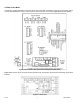
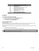
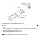
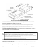
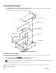
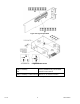
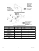
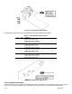
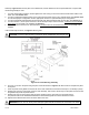

Figure 5-8. 4 Relay Output Option Board
The table below shows which jumpers are assigned to each relay. Defaults have asterisks.
Table 5-3 4 Relay Board Jumper Selection
S1 S2 FUNCTION
A, C* A, C* Assigns SP1 to Relay 1 (P6)
Assigns SP2 to Relay 2 (P7)
Assigns SP3 to Relay 3 (P18A)
Assigns SP4 to Relay 4 (P18B)
B, D A, C Assigns SP1 to Relay 3 (P18A)
Assigns SP2 to Relay 2 (P7)
Assigns SP3 to Relay 1 ( P6)
Assigns SP4 to Relay 4 (P18B)
B, D B, D Assigns SP1 to Relay 3 (P18A)
Assigns SP2 to Relay 4 (P18B)
Assigns SP3 to Relay 1 ( P6)
Assigns SP4 to Relay 2 ( P7)
A, C B, D Assigns SP1 to Relay 1 (P6)
Assigns SP2 to Relay 4 (P18B)
Assigns SP3 to Relay 3 (P18A)
Assigns SP4 to Relay 2 (P7)
Figure 5-9. Analog Output Option Board
5.2.4 Panel-Mount Assembly
The meter can be mounted in a panel so that the front of the meter is flush with the vertical panel surface. Panel mounting
can be seen as simply “sandwiching” the panel between the inner case and the outer sleeve in the last phases of
CF 156 14 M2544/N/0505