
Manual
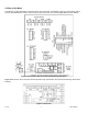
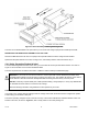
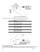

CONNECTOR # DESCRIPTION
P1 AC Power Connector or DC Power Connector
P2 External I/O Connector
P3 Input Connector
J4 Optional RS-232/RS-485 or Ethernet Connector
P5 Optional Analog Output Connector
P6 Optional Form-C Relay #1 Connector
P7 Optional Form-C Relay #2 Connector
P9 Input Connector
P18A Optional Form-C Relay #3 Connector
P18B Optional Form-C Relay #4 Connector
Table 4-1. Rear Connector Descriptions
5.0 SETUP
5.1 Conditions Requiring Disassembly
You may need to remove the sleeve or open the unit for several reasons:
1. To inspect the rating label on the case (Section 5.2.1).
2. To install optional output board(s) (Section 5.2.2).
3. To mount the unit in a panel (Section 5.2.4).
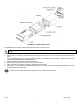
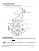
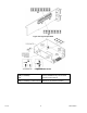
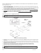
5.2 Assembly/Disassembly
OPENING THE UNIT
Your unit is fully assembled, but not wired. See Section 7 for wiring connection for power and sensor inputs. In most
cases, if you have ordered optional boards with the meter, these boards will already be installed.
You will need to remove only the rear cover to complete wiring, but you will have to open the meter to do one or more of
the following:
a. Install optional boards. See Section 5.2.2.
b. Access jumpers on the Main and optional boards. See Section 5.2.3.
WARNING!: You must disconnect and turn-off the power and connector signals before accessing the unit and
installing optional boards. Failure to do so may result in injury!
CF 156 8 M2544/N/0505