DFI INFINITY B HIGH PERFORMANCE DIGITAL FORCE INDICATOR USER’S GUIDE www.cooperinstruments.
CONTENTS NOTES, WARNINGS AND CAUTIONS .......................................................................................1 1.0 INTRODUCTION ....................................................................................................................1 1.1 Description ...................................................................................................................................... 1 1.2 Features ....................................................................................
7.5 Cold Junction Compensation Board Installation for Thermocouples ..................................... 24 7.5.1 Cold Junction Compensation Board Wiring ........................................................................ 25 7.5.2 Thermocouple Wire Colors ................................................................................................... 25 7.6 Connecting Main AC Power ......................................................................................................... 26 7.
25.0 COMMUNICATION CONFIGURATION FLOWCHART .....................................................59 26.0 COMMUNICATION MENU CONFIGURATION: (COMM) ..................................................59 26.1 COM.PAR Enter COMMUNICATION PARAMETERS Submenu: .......................................... 60 26.2 bUS.FMt Enter COMMUNICATION BUS FORMAT Submenu: .............................................. 61 26.3 dAt.FMt Enter COMMUNICATION DATA FORMAT Submenu .............................................. 63 26.
32.1.12 Flashing “dP OVF” (Decimal Point Overflow) ................................................................. 73 32.2 Troubleshooting Guide............................................................................................................... 73 33.1 Current Input ............................................................................................................................... 74 33.2 Voltage Input ..................................................................................
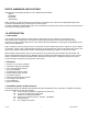
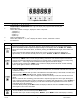
NOTES, WARNINGS AND CAUTIONS Information that is especially important to note is identified by these labels: • NOTE • WARNING • CAUTION • IMPORTANT NOTE: provides you with information that is important to successfully set up and use the Programmable Digital meter. CAUTION or WARNING: tells you about the risk of electric shock. CAUTION, WARNING or IMPORTANT: tells you of circumstances or practices that can affect the meter’s functionality and must refer to accompanying documents. 1.0 INTRODUCTION 1.
Choose between Ethernet or Serial Communication option per meter. Serial communications come with one 6 ft. communications cable with phone plug termination. Configuration Software and latest Operational Manual are available at the website listed in this manual.
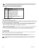
When you ordered your meter, you will receive the following items in the shipping box: QTY DESCRIPTION 1 Unit in a Mounting Sleeve with Gasket 1 Front-Panel Button Cover 1 Power Connector (orange - P1) AC version shown 2 Input Connectors (gray - P3 and P9) 1 Rear Protective Cover with Screw 1 20-Socket Ribbon Connector (P2 Connector) 2 Panel-Mounting Gaskets (1 Spare) 1 Operator’s Manual Other items may also be in the box depending on the options ordered.
3.0 SAFETY CONSIDERATIONS 3.1 Safety Considerations This device is marked with the international caution symbol. It is important to read this manual before installing or commissioning this device as it contains important information relating to Safety and EMC (Electromagnetic Compatibility). Unpacking & Inspection Unpack the instrument and inspect for obvious shipping damage. Do not attempt to operate the unit if damage is found.
Figure 4-1. Front Detail ITEM 1 2 3 4 DESCRIPTION or 6-digit, 9 segment, alphanumeric 0.68” high LED display with programmable decimal point. SETPOINT LED These LEDs, labeled 1 through 4, display the status of setpoints. 1 (Setpoint 1) 2 (Setpoint 2) 3 (Alarm 1) 4 (Alarm 2) UNIT OF DEGREE LED These LEDs, labeled oC, oF, and oK display the status in Celcius, Fahrenheit or Kelvin. 5 Pushbuttons BUTTON Function in Configuration Mode • This button functions only in Run Mode.
BUTTON Function in Configuration Mode Firmware Version Number and only after applying the power. Use ‘▲/MAX’ to select “MENU 2” or “MENU 1” the default modern Menu Navigation option. Press ‘MENU’ button again to store your Menu selection. If "MENU 2" is selected, users will be prompted to choose one of these three available Display Colors: "GREEN", "AMbER" or "REd". • Use this button to advance/navigate to the next menu item.
4.2 Rear of the Meter The following is a brief description of each part of the rear of the meter. The labeling on the top of the mounting sleeve (not the case) identifies the location of the connectors found at the rear of the meter. Figure 4-2 shows this labeling. Figure 4-2. Connector Label (AC-Powered and DC-Powered Detail) Figure 4-3 shows the rear of the meter with the optional 4-relay output board, ethernet board and analog output board installed. Figure 4-3.
CONNECTOR # P1 P2 P3 J4 P5 P6 P7 P9 P18A P18B DESCRIPTION AC Power Connector or DC Power Connector External I/O Connector Input Connector Optional RS-232/RS-485 or Ethernet Connector Optional Analog Output Connector Optional Form-C Relay #1 Connector Optional Form-C Relay #2 Connector Input Connector Optional Form-C Relay #3 Connector Optional Form-C Relay #4 Connector Table 4-1. Rear Connector Descriptions 5.0 SETUP 5.
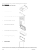
Figure 5-1. Meter Exploded View Using Figure 5-1 as a guide, follow these simple instructions to open the unit: IMPORTANT: Turn-off the power and input signals from the unit before proceeding. Failure to do so may result in injury! 1. Remove the cover mounting screw that secures the rear protective cover to the unit, and remove the Rear Protective Cover. If you are simply wiring the unit – but not checking jumpers or installing or removing boards – this is as far as the unit needs to be disassembled.
Figure 5-2. Board Assembly Removing/Installing Detail The meter is now disassembled to the point where you can check and configure jumpers and install option boards. REINSERTING THE MAIN BOARD ASSEMBLY INTO THE CASE Reinsert the Main Board into the case once jumpers and optional boards have been configured and installed. Spread the side-panel detents of the case, see Figure 5-2, and carefully slide the main board all the way in. 5.2.
5.2.2 Optional Board(s) Installation To install optional printed circuit board(s): 1. “Reveal the Main Board” (refer to Section 5.2, Disassembly). 2. Using Figure 5-3 as a reference, insert option board(s) into the corresponding connector(s) on the main board. Each circuit board is keyed to fit in its own position. Figure 5-3. Optional Board Locations 5.2.3 How to Access Jumpers To gain access to jumper S1 and S2 used to configure input type remove the mounting sleeve.
Figure 5-4. Signal Input Board Figure 5-5. Main Board Unlocks Pushbutton Programming S3A S3B (not installed) Factory Calibration only, do not install. Unlocks Lockout menus S3C S4A (installed) + solder-switch B Selects 10 Vdc Sensor Excitation (default) S4A (not installed) + solder-switch A Selects 24 Vdc Sensor Excitation Table 5-1.
Figure 5-6. Ethernet Option Board Figure 5-7. RS-232/RS-485 Option Board JUMPER S1-A S1-B S2-A S3-A (CLOSE FOR TERMINAL RESISTOR) S3-B S3-C (CLOSE FOR TERMINAL RESISTOR) S3-D S3-E (CLOSE FOR RTS TRUE) S4 (CLOSE FOR CONTINUOUS MODE) RS232 CLOSE OPEN OPEN OPEN RS485 HALF DUPLEX OPEN CLOSE CLOSE * RS485 FULL DUPLEX OPEN OPEN CLOSE * OPEN OPEN CLOSE * OPEN * OPEN * CLOSE OPEN OPEN OPEN OPEN * * * = optional, select as required. Table 5-2.
Figure 5-8. 4 Relay Output Option Board The table below shows which jumpers are assigned to each relay. Defaults have asterisks.
assembly. Figure 5-10 shows the panel cutout dimensions, and the dimensions for the panel thickness. It requires that the following already be done: 1. Your line voltage rating has been checked against the meter rating on the Product ID and serial number label on the meter case. See Section 5.2.1. 2. You have configured all jumpers-those on the main board as well as those on any optional boards. See Section 5.2.
11. Set P1, the AC power connector, aside and connect or reconnect all other connectors to the back of the meter using Figure 4-3 in Section 4.2 as guides. Connect P1 last. The P1 connector is “keyed”; it is shaped in such a way that it fits only the J1 male pins. 12. Replace the rear protective cover and secure it with the cover mounting screw. Your meter is now ready for operation and you can turn-on the power. WARNING: The unit becomes active as soon as it is connected to a power source.
6.3 VOLTAGE/PROCESS VALUE Input: 6.3.1 For ± 50mV, 0-100mV ranges: S1_K; S2_A/B/G/H, jumpers are closed as shown: NOTE: For some applications, the internal excitation is required; install jumpers G and H on S2 (as factory preset). If the external excitation is used, then remove jumper G only. These configurations are also applied to other Voltage/Process Input ranges. 6.3.2 For ± 500mV, 0-1V ranges: S1_K/E/F; S2_G/H, jumpers are closed as shown: 6.3.
6.5.2 For ±50mV, 0-100mV ranges with External Excitation: S1_L; S2_A/B/H, jumpers are closed as shown: 6.5.3 For ± 500mV, 1V ranges with Internal Excitation: S1_L/E/F; S2_G/H, jumpers are closed as shown: 6.5.4 For ± 500mV, 1V ranges with External Excitation: S1_L/E/F; S2_H, jumpers are closed as shown: 6.5.5 For ± 5V, 0-10V ranges with Internal Excitation: S1_L/C/D; S2_G/H, jumpers are closed as shown: 6.5.
6.5.10 For 0-20mA or 4-20mA range with External Excitation: S1_K; S2_A/B/C/D/H, jumpers are closed as shown with External Excitation: 6.5.11 POTENTIOMETER Input: S1_K/G/C/D; S2_C/G/H jumpers are closed as shown: Jumper Function S4A (installed) + solder jumper B Selects 10 Vdc Sensor Excitation (default) S4A (not installed) + solder jumper A Selects 24 Vdc Sensor Excitation Table 6-1. Sensor Excitation Main Board Jumper Selection Refer to Figure 5-5 for solder jumper locations. 7.
Figure 7-2. Current Input with Sensor Excitation Figure 7-3. Voltage Input Without Sensor Excitation Figure 7-4. 3-Wire Voltage Input With Sensor Excitation Figure 7-5.
Figure 7-6. Potentiometer Connections with Internal Power Supply and Ratio Measurement. Figure 7-7. Potentiometer Connections with External Power Supply and Ratio Measurement (Remove Jumper S2-G) 7.3 Signal Input Connections - Temperature The following Figures (7-8 through 7-11) show the connections for Thermocouple and RTD Inputs. Figure 7-8. Directly-Connected Thermocouple Figure 7-9.
Figure 7-10. RTD Connections with 3-wire RTD Figure 7-11. RTD Connections with 4-wire RTD 7.4 Signal Input Connections - Strain The following Figures (7-12 through 7-19) show the connections for voltage, current and potentiometer inputs: Figure 7-12. Current Input Without Sensor Excitation Figure 7-13.
Figure 7-14. Voltage Input Without Sensor Excitation Figure 7-15. 3-Wire Voltage Input With Sensor Excitation Figure 7-16. 4-Wire Voltage/Bridge Input With Sensor Excitation Figure 7-17.
Figure 7-18. Potentiometer Connections with Internal Power Supply and Ratio Measurement Figure 7-19. Potentiometer Connections with External Power Supply and Ratio Measurement (Remove jumper S2-G) 7.5 Cold Junction Compensation Board Installation for Thermocouples To setup the rear protective cover with the P3 and P9 connectors (and Cold-Junction Compensation Board), proceed with the following (Refer to Figure 7-20). 1) Obtain P3 and P9 connectors and the thermocouple rear protective cover.
7.5.1 Cold Junction Compensation Board Wiring Figure 7-21 shows the wiring hookup for thermocouples. Use the following table to determine which colored wired get connected to the positive and negative terminals. Note: Positive (+) and Negative (-) wiring designations are molded into the plastic cover. Figure 7-21. Directly-Connected Thermocouple 7.5.2 Thermocouple Wire Colors Table 7-1.
T/C TYPE J K T E N R S B DIN J T/C TYPE J K T E N R S B DIN J FRANCE WIRE COLORS + LEAD - LEAD Yellow Black Yellow Purple Yellow Blue Yellow Purple No Standard-See USA Yellow Green Yellow Green Use Copper Wire Red Blue GERMANY WIRE COLORS + LEAD - LEAD Red Blue Red Green Red Brown Red Black No Standard-See USA Red White Red White Red Gray Red Blue JAPAN WIRE COLORS + LEAD - LEAD Red White Red White Red White Red White No Standard-See USA Red White Red White Red Gray Red Blue UNITED KINGDOM WIRE COLORS
USA WIRING CODE Black White Green EUROPE WIRING CODE CONNECTION Brown ~ AC Line (L) Blue ~ AC Neutral (N) Green/Yellow ~ AC Protective Ground Figure 7-22. AC Connector Wiring at P1 P1 PIN # ON ORANGE CONNECTOR 1 2 3 You are now ready to proceed with setting setpoints as described in Section 8. 7.7 Connecting Main DC Power Connect the DC main power connections as shown in Figure 7-23. CAUTION: As mentioned in Section 3.1, the meter has no power ON/OFF switch. The meter will be ON when power is applied.
8.0 SETPOINT SETTINGS MENU FLOWCHART Once this ‘SETPTS’ button is pressed, each of the four setpoints’ value will be displayed for approximately 10 sec. in the sequence of this Setpoint Setting Menu Flowchart, unless the ‘SETPTS’ is repeatedly pushed or setpoint is being edited. 9.0 ACTIVE BUTTONS: ‘SETPTS’, ‘▲/MAX’, ‘►/MIN’. Press ‘SETPTS’ Press ‘▲/MAX’ Press ‘SETPTS’ CF 156 1) The display shows "SP1" momentarily then "00000.0" or previous setpoint value with first digit flashing.
Press ‘▲/MAX’ Press ‘▲/MAX’ Press ‘►/MIN’ Press ‘SETPTS’ Press ‘SETPTS’ "SP 3", "SP3’s value" "SP 4", "SP4’s value" "RUN". 4) Enables the user to select and modify first, or flashing digit of the setpoint value. 5) The digit will change in this following cycle: 0 to 9, - (minus sign). 6) To select the next downward digit to modify. 7) Display shows "StOREd" stored message momentarily (to save the new value if a change was made) then advances to next item "SP2" Setpoint 2.
10.0 MAIN MENU CONFIGURATION FLOWCHART 1) Once lockout security ID code is set “enable”, the Menu will not be displayed through Main Configuration Menu navigation. 2) To regain access to the locked Menu, user will be prompted for security ID code at LCk.CNF Menu.
11.0 INPUT TYPE MENU FLOWCHART: (INPUT) 12.0 INPUT TYPE SELECTION: (INPUT) 12.1 Input Type: (Thermocouple) INPUt Press ‘MENU’ Press ‘RESET/ENTER’ Press ‘▲/MAX’ ENTER INPUT TYPE MENU: 1) Display shows "INPUt" Input Menu. 2) Display flashes "VOLt" or previous stored input type. 3) Scroll through the available following input type selection list. Display flashes: "VOLt" (DC Voltage) "CURRNt" (DC Current) "bRIdGE" (Bridge) "POt" (Potentiometer) "tC" (Thermocouple) "Rtd" (RTD).
below for types). If the display matches your choice of Thermocouple. Go to Step 8. Press ‘▲/MAX’ 7) Scroll through the available thermocouple types to the selection of your choice. Press ‘RESET/ENTER’ 8) Display shows "StOREd" stored message momentarily and then advances to the "RdG.CNF" Reading Configuration Menu. Thermocouple Types: Display: J J tC K k tC T t tC E E tC N N tC DIN J dNJ tC R R tC S S tC B b tC 12.
VOLt Press ‘▲/MAX’ Press ‘RESET/ENTER’ Press ‘RESET/ENTER’ “VOLt” DC VOLTAGE SUBMENU: 4) Scroll through the available selection to "VOLt" (flashing). 5) Display shows "VOLt" again, but not flashing. 6) Display flashes "UN IPOL" unipolar (default) or previously stored selection of voltage input type "bI POL" bipolar. You must choose bi-Polar or uni-Polar before selecting Bridge or Potentiometer Press ‘▲/MAX’ 7) Scroll through the 2 available voltage input types to the selection of your choice.
Press ‘MENU’ Press ‘RESET/ENTER’ Press ‘▲/MAX’ 1) Display shows "INPUt" Input Menu. 2) Display flashes "VOLt" (default) or previous stored input type. 3) Scroll through the available following input type selection list. Display flashes: "VOLt" (DC Voltage) "CURRNt" (DC Current) "bRIdGE" (Bridge) "POt" (Potentiometer) "tC" (Thermocouple) "Rtd" (RTD) If the displayed input type is "bRIdGE", press ‘RESET/ENTER’ to skip to Step 6 ("bRIdGE" stops flashing).
13.0 READING CONFIGURATION MENU AND FLOWCHART: (RDG.
14.0 READING CONFIGURATION MENU: RdG.CNF Press ‘MENU’ Press ‘RESET/ENTER’ Press ‘MENU’ Configuration 14.1 RD.SC.OF Press ‘RESET/ENTER’ Press ‘RESET/ENTER’ Press ‘▲/MAX’ ENTER READING CONFIGURATION MENU: 1) Twice though Main Menu items and display shows "RdG.CNF ". 2) Display shows "Rd.SC.OF " Reading Scale & Offset menu. 3) Scroll through the following sequence of available Reading Menu selection list: "Rd.SC.OF" (Reading Scale & Offset) "Unt.
OFFSET MENU CONFIGURATION. Press ‘RESET/ENTER’ Press ‘▲/MAX’ dIRECt Press ‘RESET/ENTER’ Press ‘RESET/ENTER’ Press ‘RESET/ENTER’ Press ‘▲/MAX’ & ‘►/MIN’ Press ‘RESET/ENTER’ Press ‘RESET/ENTER’ Press ‘▲/MAX’ & ‘►/MIN’ Press ‘RESET/ENTER’ Enter READING SCALE & OFFSET FORMAT SUBMENU: 7) To enter Reading Scale & Offset Format Configuration Submenu. Display shows "StOREd" stored message momentarily then flashes "dIRECt" (default) Direct format or previous format selection, if your option of "Rd.SC.
Press ‘RESET/ENTER’ 22) Display shows "xxxxxx" some 6-digit number, represents the value of "INPUt 1" as taken from live input source measurement for desired value. Press ‘RESET/ENTER’ 23) Display shows "REAd 1" Item #2 of coordinate #1. Press ‘RESET/ENTER’ 24) Display shows "xxxxxx" some 6-digit number with first digit flashing, represents the value of "REAd 1" item #2 of coordinate #1. Press ‘▲/MAX’ & ‘►/MIN’ 25) Use ‘MAX’ and ‘MIN’ buttons to enter new value of "REAd 1".
Press ‘RESET/ENTER’ Press ‘RESET/ENTER’ Press ‘▲/MAX’ Press ‘RESET/ENTER’ Press ‘RESET/ENTER’ Press ‘▲/MAX’ Press ‘RESET/ENTER’ 14.4 FILtER Press ‘RESET/ENTER’ Press ‘MENU’ CNt by Press ‘RESET/ENTER’ Press ‘▲/MAX’ Press ‘RESET/ENTER’ FILt.tP Press ‘RESET/ENTER’ Press ‘▲/MAX’ Press ‘RESET/ENTER’ FILt.Tm Press ‘RESET/ENTER’ Press ‘▲/MAX’ Press ‘RESET/ENTER’ CF 156 5) Display shows "dP.ActV" Decimal Point Effect Selection menu.
14.5 FLS.dSP Press ‘RESET/ENTER’ Press ‘RESET/ENTER’ Press ‘MENU’ Press ‘▲/MAX’ Press ‘RESET/ENTER’ 14.6 bRIGHt Press ‘RESET/ENTER’ Press ‘▲/MAX’ Press ‘RESET/ENTER’ CF 156 Enter FLASHING DISPLAY CONTROL Submenu: 23) Display shows "SP1.FLS" Setpoint 1 Flashing. 24) Display flashes "dISAbL" disable (default) or previous selection of control option. 25) Scroll though next available Setpoint/Alarm Display Flashing selections: "SP1.FLS", "SP2.FLS", "AL1.FLS" and "AL2.FLS".
15.
16.0 INPUT CONFIGURATION MENU: (INP.CNF) INP.CNF Press ‘MENU’ Press ‘RESET/ENTER’ Press ‘MENU’ 16.1 L IN.FRE ENTER INPUT CONFIGURATION MENU: 1) Three times though Main Menu items and display shows "INP.CNF". 2) Display shows "L IN.FRE" Line Frequency submenu. 3) Scroll through the following sequence of available Input Configuration Menu selection menu: "L IN.FRE", "Ad.RAtE", "MOdE", and "IN.SC.OF" (Line Frequency, Analog to Digital Rate, Input Mode and Input Scale & Offset).
In case of "tC" input type: Press ‘RESET/ENTER’ 10) Display shows "tC.CO.JC" Cold-Junction Compensation for "tC" Thermocouple input type. Press ‘RESET/ENTER’ 11) Display flashes "ENAbLE" as default or previous selection. Press ‘▲/MAX’ 12) To select either "ENAbLE" or "dISAbL" for your choice of setup. Press ‘RESET/ENTER’ 13) Display shows "C.JUN.OF" Cold-Junction Offset Adjustment menu. Press ‘RESET/ENTER’ 14) Display flashes "dISAbL" as default. 16.3.
Adjustment. *The following Step 17 is a safety measure to prevent unintentional calibration. Press ‘▲/MAX’ 17) Display still shows "CAL 0" Submenu. Press ‘RESET/ENTER’ 18) Display shows "StOREd" stored message (meaning the calibration is complete) momentarily and advances to "IN.SC.OF" Input Scale & Offset configuration Submenu. In case of "bRIdGE" input type: Press ‘RESET/ENTER’ 19) Display shows "bRdG.LM" Bridge Limit function menu. Press ‘RESET/ENTER’ 20) Display flashes "NORMAL" or the previous setting.
ON.L INE Press ‘RESET/ENTER’ Press ‘▲/MAX’ 30) Display flashes "ON.L INE" On line method. 31) Scroll between 2 available selections: "ON.L INE" or "MANUAL" for the configuration option of your choice. If your choice of selection is "MANUAL", skip to Step 40). Press ‘RESET/ENTER’ 32) Display stops flashing and shows "ON.L INE". Press ‘RESET/ENTER’ 33) Display shows "INPUt 1" Item #1 of coordinate #1.
Input Signal Range 0-50mV 0-100mV 0-1V 0-5V 1-5V Scale Input 1 Value 000000 000000 000000 000000 010000 Scale Input 2 Value 050000 100000 100000 050000 050000 Input Signal Range 0-10V 0-50V 0-100V ±5V ±50V Scale Input 1 Value 000000 000000 000000 -50000 -50000 Scale Input 2 Value 100000 050000 100000 050000 050000 Table 16-2. Factory Calculated Scale Factors Table 1-6V 010000 060000 For the purpose of this procedure, we will use an input of 0-50 mVdc and scale the meter to display 0 to 2500.0.
17.0 MULTI-POINT SCALE & OFFSET MENU CONFIGURATION FLOWCHART 18.0 MULTI-POINT SCALE & OFFSET MENU CONFIGURATION: (MP.SC.OF) For proper Multipoint Scale & Offset Configuration, user must enter the first Input (Input0) with least value, then the next one with the greater value and so forth...
This scaling method based on 2 Input values entered with 2 corresponding readings. Up to 10 Linearization Points can be selected to customize the transducer curve. MP.SC.OF Press ‘MENU’ Press ‘RESET/ENTER’ Press ‘RESET/ENTER’ Press ‘▲/MAX’ Press ‘RESET/ENTER’ Enter MULTI-POINT SCALE & OFFSET MENU: 1) Four times or scroll though Main Menu items, select and enter "MP.SC.OF". 2) Display shows "NUM.PNt" Number of Points menu.
To scale "MANUAL", calculate inputs based on transducer specifications and manually enter them via on the front panel push buttons. The following example assumes load cells with this specification: Maximum Load:....................................................................100.0 lb Output ................................................................................3.0 mV/V Sensor Excitation ......................................................................10 V Maximum Sensor Output = 3.
DISPLAY READING VALUES (y = ax + b) Yrd = (SCALE).Xin + (OFFSET) MP.SC.OF IN.SC.OF Rd.SC.OF disable disable RS.Xin + RO enable disable disable IS.Xin + IO enable disable disable MS.Xin + MO enable disable RS.(IS.Xin + IO) + RO enable enable disable IS.(MS.Xin + MO) + IO enable enable disable RS.(MS.Xin + MO) + RO enable enable RS.[IS.(MS.Xin + MO) + IO] + RO enable enable enable Table 18-2. Reading / Input Scale & Offset Calculation Table READING/INPUT SCALE & OFFSET MODE 19.
OUt.CNF Enter OUTPUT CONFIGURATION MENU: Press ‘MENU’ 1) 5 times or scroll though main Menu until Display shows "OUt.CNF" Output Configuration Menu. 20.1 ANA.OUt Press ‘RESET/ENTER’ Press ‘RESET/ENTER’ Press ‘▲/MAX’ 2) Display shows "ANA.OUt" Analog Output Configuration submenu. 3) Display flashes "dISAbL" (Default) or previous setting option. 4) Select "ENAbLE" to setup Analog Output if your controller is equipped with the optional Analog Output board.
20.2 Ot.SC.OF Enter OUTPUT SCALE & OFFSET CONFIGURATION Submenu: READING 1 Press ‘RESET/ENTER’ Press ‘RESET/ENTER’ Press ‘▲/MAX’ & ‘►/MIN’ Press ‘RESET/ENTER’ 10) Display shows "REAd 1" Reading 1 menu. 11) Display flashes 1st digit of previous "REAd 1" value. 12) Enter "REAd 1" value. (Example 000000). 13) Display advances to "OUt 1" Output 1 menu. OUTPUT 1 Press ‘RESET/ENTER’ Press ‘▲/MAX’ & ‘►/MIN’ Press ‘RESET/ENTER’ 14) Display flashes 1st digit of previous "OUt 1" value. 15) Enter "OUt 1" value.
22.0 SETPOINT CONFIGURATION MENU: (SP.CNF) Setpoints 1 through 4 can be configured for a very large variety of zone and level signaling. SP1 and SP2 have balanced configurable hysteresis and are non-latching, suitable for control-level signaling. SP3 and SP4 are often used as Alarm1 and Alarm2, because they have single-sided hysteresis and can be configured for latching action.
23.0 ALARM CONFIGURATION MENU FLOWCHART 24.0 ALARM CONFIGURATION MENU: (AL.CNFG) SP3 and SP4 are often used as Alarm1 and Alarm2, because they have single-sided hysteresis and can be configured for latching action. The levels of these Setpoints are entered during run mode via the front-panel pushbuttons (refer to Setpoint Settings Menu Configuration Section 8).
Alarm configuration is used to select or setup: • The Active Zone for each alarm point (SP3 or AL1, SP4 or AL2) to above or below the setting with "Act IVE" submenu. • Independent or ganged operation for SP3 / AL1 or SP4 / AL2 whether or not they should latch once triggered, "LAtCH" submenu. • Whether the normal state of Output Collector or Relay is opened or closed with "N.StAtE" submenu. • Following Alarm modes: process (no deviation), high-deviation, low-deviation and band deviation with "AL.
ACt IVE Press ‘RESET/ENTER’ Press ‘RESET/ENTER’ Press ‘▲/MAX’ Press ‘RESET/ENTER’ LAtCH Press ‘RESET/ENTER’ Press ‘▲/MAX’ N.StAtE Press ‘RESET/ENTER’ Press ‘RESET/ENTER’ Press ‘▲/MAX’ 5) Display shows "ACt IVE" Alarm Active State submenu. 6) Display flashes "AbOVE" Above Alarm/Setpoint active state option or previous setting. 7) Scroll to select 2 available options for your choice "AbOVE" or "bELOU" (below) Alarm/Setpoint Active State.
There are 4 types of Alarm modes/Deviation Functions which can alter the alarm response as flowing illustrations: All horizontal axes represent time line. “PROC.” : Process Deviation (No Deviation) “HI dEV” : High Deviation for both Active Above and Active Below “LO dEV” : Low Deviation for both Active Above and Active Below “bNd.
Press ‘RESET/ENTER’ Press ‘▲/MAX’ 24.2. AL 2.CNF Press ‘RESET/ENTER’ Press ‘RESET/ENTER’ 24.3 AL db 15) Display flashes "PROC." Process (No Deviation) mode or previous selection. 16) Scroll 4 available following options for your choice of Alarm Mode: "PROC." (Process Deviation), "HI dEV" (High Deviation), "LO dEV" (Low Deviation) and "bNd.dEV" (Band Deviation). Enter ALARM 2 CONFIGURATION Menu: 17) Display shows "StOREd" stored message momentarily and then advance to "AL 2.
25.0 COMMUNICATION CONFIGURATION FLOWCHART 26.0 COMMUNICATION MENU CONFIGURATION: (COMM) Communication Operation Requirement: Communication Option Board must be installed as either equipped by model or by user-option add-on upgrade.
Purchasing the controller with Serial Communications permits an instrument or more meters to be configured or monitored remotely from an IBM PC compatible computer using software available from the website or on the CD-ROM enclosed with your shipment. For complete and detail instructions for the use of the Communication Option, refer to the Serial Communication Reference Manual.
Press ‘RESET/ENTER’ 10) Display shows "StOREd" stored message momentarily and then advances to the "StOP" Stop Bit setting submenu. Press ‘RESET/ENTER’ 11) Display flashes "1b It" 1-Bit or previous setting. Press ‘▲/MAX’ 12) Scroll through and select 2 available following options: "1b It" (1-Bit) or "2b It"(2-Bit). Press ‘RESET/ENTER’ 13) Display shows "StOREd" stored message momentarily and then advances to the "bUS.FMt" Bus Format submenu. 26.2 bUS.
ECHO Press ‘RESET/ENTER’ 20) Display shows "StOREd" stored message momentarily and then advances to the "ECHO" Line Feed setting submenu. • When valid commands are sent to the instrument, this determines whether the command will be echoed to the Serial Bus. Use of "ECHO" is recommended in most situations, especially to help verify that data was received and recognized by the controller.
• Message Hand Shake: The RTS (Request To Send) line from the host controller is checked when the device is ready to send measurement data. If the RTS is true, it sends the complete message data without interruption even if RTS goes false in the middle of transmission. If RTS is false, it skips sending the data completely and continues with the next measurement. • Character Hand shake: The device checks the RTS input before sending each character and sends characters only while RTS is true.
button. • For Universal meters, there is a list of the transmitted character (Hex number value) corresponding for each of the sixteen (16) possible Setpoint/Alarm (SP1, SP2, AL1/SP3 and AL2/SP4) states. Refer to STATUS CHARACTER FORMATS/Alarm Status Characters Chapter of Serial Communications Option Manual for detail description and listing Table. Press ‘RESET/ENTER’ 34) Display flashes "NO" No (Alarm Status Character excluded from Data String as default) option or previous selection.
SEPARA Press ‘RESET/ENTER’ 51) Display shows "StOREd" stored message momentarily and then advances to the "SEPARA" Separator Selection submenu that determines whether different data types included in Data String and sent from the device will be separated by spaces or by Carriage Returns. Press ‘RESET/ENTER’ 52) Display flashes "SPACE" Space separator as default or previous selection. Press ‘▲/MAX’ 53) Scroll and select "SPACE" or "CR" Carriage Return Option for your choice of Data String Format.
27.0 DISPLAY COLOR SELECTION MENU FLOWCHART: 28.0 DISPLAY COLOR SELECTION MENU: (COLOR) COLOR Press ‘MENU’ CF 156 Enter COLOR SELECTION MENU: 1) Nine times, if Communication Option Board installed, otherwise just eight times. Display shows "COLOR" Color Selection Menu that allows user to select the color of the LED display for either normal mode or under alarmed condition.
28.1 N.COLOR Enter NORMAL COLOR SUBMENU Press ‘RESET/ENTER’ 2) Display shows "N.COLOR" Normal Color submenu that allows user to change normal Display’s color. If necessary to access the other following submenus: "SP1.CLR", "SP2.CLR", "AL1.CLR" or "AL2.CLR". Use or Press ‘MENU’ button. Press ‘RESET/ENTER’ 3) Display flashes "GREEN" Green color (default) or previous selection. Press ‘▲/MAX’ 4) Scroll through the available following colors: "GREEN", "REd" or "AMbER" for your color choice of Display.
29.
30.0 LOCKOUT (ACCESS SECURITY) CONFIGURATION MENU • To prevent unauthorized tampering with the setup parameters, this instrument provides protection by requiring the user to enter the ID (Access Security) Code before allowing access any locked menu item on Main menu. • The locked menu will be skipped and invisible during Menu Navigation, however Display will show the locked setpoint and value but editing mode is disabled (first digit is not flashing).
The meter case label gives the names (abbreviated functions) of each of the twenty pins of P2, the center-bottom connector. Refer to Figure 30-1. Figure 30-1. Connector Label Detail 31.1 TARE (PIN 1) Tare is available when P2-1 and P2-4 are connected to a momentary contact switch. This feature allows you to automatically zero your meter when the switch is activated. Tare is not available for temperature meters. 31.
31.8 +5 V (PIN 8) Up to 20 mA is available for driving external devices, but isolation should be provided if there is a possibility of common mode (ground) currents, since this supply is NOT isolated from the signal input. 31.9 DISPLAY HOLD (PIN 9) Grounding this pin to P2-7 freezes the display value. However, the meter continues to take new samples and update the other outputs, such as Analog Output, Setpoints/Alarms, and Peak/Valley. 31.
Figure 30-2 For Setpoint Transistors 32.0 TROUBLESHOOTING - DISPLAY MESSAGES AND TROUBLESHOOTING GUIDE A flashing alpha-numeric message in the display generally indicates an incorrect combination of jumpers and/or configuration values. 32.1 Error Mode Messages 32.1.1 Flashing “999999” (Numerical Overflow) The maximum number of counts in the display cannot exceed -99999 or 999999.
32.1.9 Flashing “R OVSC” (Reading Overscale) This display occurs when the reading scale and/or offset applied to the input signal causes the display to go into a numerical overflow. 32.1.10 Flashing “CB OVF” (Count By Overflow) When a display value near the maximum display capability is forced into a numerical overflow by changing the CNT BY menu (for example, the display reads 999997 and the count by is changed from 001 to 005 and rounds the display up to 1000000). 32.1.11 Flashing “UOM.
broken or otherwise opened. Check thermocouple or RTD wiring. “I OVSC” POSSIBLE CAUSE: TO CORRECT: “R OVSC” POSSIBLE CAUSE: TO CORRECT: “CB OVF” POSSIBLE CAUSE: TO CORRECT: “SERIAL” POSSIBLE CAUSE: TO CORRECT: The input scale and/or offset values chosen are large enough to drive the display into numerical overflow. Reduce the input and/or the input scaling/offset. Refer to “IN.SC.OF” in Section 16.4.
For accurate full scale measurements below -40 degrees, you may need to complete the full scale cold junction calibration procedure (Refer to Section 16.3.1, Special Cold-Junction Calibration). Calibration: NIST #135, DIN 43710 Reference Junction: Either a remote ice-point cell or an oven can be used in place of the Cold-Junction Compensation Board. Curvalinear correction to better than 40 dB ambient temperature rejection. 33.
resolution; 0.1% accuracy; 6 msec step response. Form -C, SPDT Relays Two relays at P6 and P7 30Vdc or 250 Vac @ 5 Amp Two relays at P18A and P18B 30 Vdc or 250 Vac @ 3 Amp (see Figure 5-9) RELAY OUTPUT, OPTIONAL: POWER RATING FOR RESISTIVE LOADS: TURNDOWN RATIO (MAX OFFSET-MIN SPAN): 1000 with 0.1% or 100 with 0.01% resolution NETWORK AND COMMUNICATIONS,OPTIONAL: ETHERNET: Standards Compliance IEEE 802.
1. Test with Analog Out (AN03) Sample Rate Process (100 mV) Rate (ms) 0 7(135) 1 14(68) 2 27(36) 3 52(19) 4 100(10) 5 142(7) TC (K type) Rate (ms) 7(135) 14(68) 27(36) 41(24) 41(24) 41(24) 2. Test with Communication (Baud Rate at 19200 bps, Continuous Mode) Sample Rate Process (100mV) TC (K type) Rate (ms) Rate (ms) 0 7(135) 7(135) 1 14(68) 14(68) 2 27(36) 27(36) 3 52(19) 33(30) 4 71(14) 33(30) 5 71(14) 33(30) 3.
Figure 33-1. Meter Housing and Panel Cutout 33.
DURING SETPOINT ADJUST (RUN MODE) OUT OF SELECTED DIGIT RANGE: NOT STORED IN EEPROM: VALUE PUT IN EEPROM: “999999” “NOSTOR” “STORED” 33.8 ITS-90 Thermocouple Tables For complete Thermocouple Tables, please refer to the Technical Reference Section : Thermocouple Reference Data. This information is located: http://omega.com/temperature/Z Temperature Handbooks, Section Z or CD-ROM, enclosed with your shipment 33.
33.11 ITS-90 RTD 392 US Table Temp oC -200 -190 -180 -170 -160 -150 -140 -130 -120 -110 -100 -90 -80 -70 -60 -50 -40 -30 -20 -10 0 10 20 30 40 50 60 70 80 90 100 110 120 130 140 150 160 170 180 190 200 Resistance 17.0787 21.4575 25.8017 30.1135 34.3948 38.6476 42.8737 47.0747 51.2522 55.4078 59.5429 63.6587 67.7565 71.8373 75.9022 79.952 83.9876 88.0096 92.0187 96.0154 100 103.9728 107.9339 111.8833 115.8209 119.7467 123.6609 127.5633 131.4539 135.3329 139.2 143.0555 146.8992 150.7312 154.5514 158.
INPUT SELECTION : INPUt VOLTAGE: VOLt Voltage type = UNIPOL Range = 100MV If choose bI POL Range = 50MV If choose different INPUt-If tC: Type = J tC If Rtd: Type = 2Pt.392 If CURRNt: Range = 0-20MA OUTPUT CONFIGURATION : OUt.CNF ANA.OUt = dISAbL If Choose ENAbLE: MOdE = VOLt OUt.tYP= UNFILt SETPOINT CONFIG: SP.CNF SP CNF=dISAbL If choose ENAbLE SP1.CNF: ACtIVE=AbOVE N.StAtTE=N.OPEN READING CONFIG : RdG.CNF Rd.SC.OF = dISAbL If choose ENAbLE = dIRECt SP2.CNF: ACtIVE=bELOU N.StAtE=N.OPEN UNt.tMP = C dEC.
LOCKOUT CONFIG : LCk.CNF (ALL DISABLED) SP1 SP2 SP3 SP4 INPUt RdG.CNF INP.CNF MP.SC.OF OUt.CNF SP.CNF AL.CNF COMM COLOR 35.0 RECORD YOUR SETUP VALUES JUMPER CONFIGURATIONS-S1 = S2 = S3 = S4 = INPUT CONFIGURATION : INP.CNF LIN.FRE= Ad.RAtE= MOdE If Choose tC: tC.CO.JC= C.JUN.OF If Choose bRIdGE: bRDG.LM= RAtIO= INPUT SELECTION : INPUt If choose VOLt UNIPOL,Range = If choose bI POL, Range = If tC: Type = If Rtd: Type = If CURRNt: Range = READING CONFIG : RdG.CNF Rd.SC.OF = If choose ENAbLE = IN.SC.
ALARM CONFIGURATION : AL.CNF AL.CNFG = If ENAbLE: AL1.CNF ACtIVE = LAtCH = N.StAtE = AL.MOdE AL2.CNF: ACtIVE = LAtCH = N.StAtE = AL.MOdE LED COLOR SELECTION : COLOR N.COLOR= SP1.CLR= SP2.CLR= AL1.CLR= AL2.CLR= LOCKOUT CONFIG : LCk.CNF (ALL DISABLED) SP1 SP2 SP3 SP4 INPUt RdG.CNF INP.CNF MP.SC.OF OUt.CNF SP.CNF AL.CNF COMM COLOR AL db = NUM.dLy = RSt AL = COMMUNICATION CONFIG : COMM: COM.PAR BAUd = PARIty = StOP = bUS.FMt SUMCHk = LN.FEEd = ECHO = STNd = MOdE = HNd.SHk = dAt.FMt AL.StAt = P.V.StAt = SNd.
Electrical Safety EN61010-1:2001 Safety requirements for electrical equipment for measurement, control and laboratory. Double Insulation Pollution Degree 2 Dielectric withstand Test per 1 min • Power to Input/Output*: 2500Vac • Power to Input/Output*: 1500Vac (Low Voltage dc Power Option**) • Relays to Power/Inputs/Outputs*: 2500Vac • Ethernet to Inputs: 1500Vac • Isolated RS232/RS485 to Inputs: 500Vac • Isolated Analog to Inputs: 500Vac Note: * Outputs = Isol. Analog, Isol.
Advance authorization is required prior to the return to Cooper Instruments. Before returning the item, contact the Repair Department c/o Cooper Instruments at (540) 349-4746 for a Return Material Authorization number. Shipment to Cooper shall be at buyer’s expense and repaired or replacement items will be shipped F.O.B. from our plant in Warrenton, Virginia. Non-verified problems or defects may be subject to a $150 evaluation charge. Please return the original calibration data with the unit.