
Manual
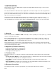

CF 147 2 version 1.1
Bold Text Bold text denotes words and phrases to note.
<Key> <Key> denotes a Keypad key.
Note: In the Specifications section the < symbol means less than and the > symbol means greater
than.
^ This symbol denotes one space (used in Automatic Weight Output section 9.1)
Items marked with indicate that the setting is available only in Full Setup and is trade critical. When
trade critical settings are changed the calibration counter will be incremented.
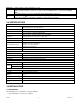
2.0 SPECIFICATIONS
Performance
Resolution
Up to 30,000 divisions, minimum of 0.25µV/division, 20 updates/second
(Trade 4000 divisions at 0.8µV/division)
Zero Cancellation ±2.0mV/V
Span Adjustment 0.1mV/V to 3.0mV/V full scale
Stability/Drift
Zero: < 0.1µV/°C (+ 8ppm of deadload max)
Span < 8 ppm/°C, Linearity < 20ppm, Noise < 0.2µVp-p
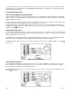
Excitation
5 volts for up to 4 x 350 or 8 x 700 ohm load cells (4-wire or 6-wire plus shield)
Maximum total load cell resistance: 1,000 ohms
A/D Type 24bit Sigma Delta with 8,388,608 internal counts
A/D Conversion Rate 20Hz with FIR filtering > 80dB
Operating Environment
Temperature: 14 to 122°F ambient
Humidity: <90% non-condensing
Storage: –4 to 122°F ambient
IP55 when panel mounted
Case Materials ABS, Silicon Rubber, Nylon, Acrylic (no halogen used)
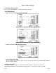
Packing Weights Basic Indicator: 0.75lb
Digital
Display LED Backlit LCD with six 0.8” high digits with units and annunciators
Setup and Calibration Full digital with visual prompting in plain messages
Digital Filter Sliding window average from 0.1 to 4.0 seconds
Zero Range Adjustable from ±2% to ±20% of full capacity
Power Input
Standard Power Input 12 to 24VDC (2.5 VA max) - ON/OFF key with memory feature
AC Wall Transformer: 110/240VAC 50/60Hz in 12VDC 0.5A out
Variants
Battery 4 x AA batteries (Alkaline or rechargeable NiMH, NiCad, etc.)
Features
GSE-LINK Data Coupling Infra-red Connector for optional GSE-LINK PC cable (to RS-232 PC port)
Correction Five point linearity correction
Outputs
RS-232 automatic transmit, network or printer outputs. Transmission rate: 2400, 4800 or 9600
baud
Assignable Function Key Unit switching, counting, manual hold, peak hold, live weight and totalizing
Drive Outputs 2 isolated transistor drive outputs (300mA total at 50VDC)
Battery Backed Time/Date
Clock
Battery life 10 years minimum
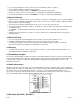
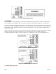
3.0 INSTALLATION
3.1 Introduction
The following steps are required to set up the indicator.
• Inspect indicator to ensure good condition.