
Manual

CF 147 13 version 1.1
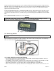
Since the instrument
uses 5V load cell
excitation, the absolute
signal voltage is:
Absolute Signal Voltage
= Excitation Voltage x Full Scale Signal = 5V x 1.0mV/V = 5.0mV
Calculating the
signal resolution:
Signal Resolution =
Absolute Signal
Voltage
Number of
Graduations
=
5.0mV
1000
divisions
= 0.005mV/division = 5µV/division
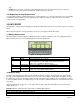
6.3 Filtering Techniques
There is a trade off between noise filtering and the step-response time of the system. The step-response is defined
as the time between placing a weight on the scale and the correct stable weight reading being displayed. This does
not affect the number of readings per second that are taken. It simply defines the amount of time that is required to
determine a final weight reading.
The FILTER setting in the instrument setup shows the amount of time over which the averaging is taken.
Increasing the averaging time will result in a more stable reading but will extend the time it takes the instrument to
settle to a final reading. Refer to FILTER (Reading Average) section 7.4.2.
6.4 Industrial vs. OIML and NTEP Modes
The instrument may be operated in Industrial, OIML or NTEP mode. (Note: For NSC requirements use the OIML
setting.) The OIML and NTEP modes restrict certain aspects of the operation of the instrument to ensure
compliance with the respective trade certified standards. For more information refer to the Calibration Counter
section below and also to the USE (Scale Use) section 7.4.2 for setup information. The following table lists the
operation differences for each of these modes.
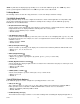
Table 2: Industrial vs. OIML and NTEP Modes
Element Industrial OIML NTEP
Underload –105% of full scale –1% or –2% of full scale
depending on zero range setting
Same as OIML
Overload 105% of full scale Full scale +9 divisions 105% of full scale
Tare No restrictions on Tare Tare values must be > 0 Tare values must be > 0 and
rounded to the nearest graduation
Test Modes Unlimited time allowed Limited to five seconds Limited to five seconds
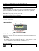
6.5. Calibration Counter
Within Setup there are a number of critical steps that can affect the calibration and/or legal for trade performance of
the instrument. If any of these steps are altered, the trade certification of the scale could be voided.
The instrument provides built-in calibration counter(s) to monitor the number of times the critical steps are altered.
The value of a counter is stored within the instrument and can only be reset at the factory. Each time a critical step
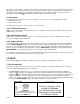
is altered, the counter will increase by one. Whenever the instrument is powered up, or setup mode is entered/
exited, the current value in the counter is displayed briefly (e.g. C00010).
Note: When the Scale Use is set to NTEP two counters will display. Refer to USE (Scale Use) section 7.4.2 for
setup information. The table below describes when the counter(s) will increment for Industrial, OIML or NTEP
modes.
Industrial OIML NTEP
The Calibration Counter
increments when trade
critical settings, marked
with , are changed. An
example of the counter is
C.00019.
The Calibration Counter
increments when trade
critical settings, marked
with , are changed. An
example of the counter is
C.00019.
The Calibration Counter increments when trade critical
settings in the Calibration (CAL) menu, marked with , are
changed. An example of the counter is C.00010.
The Configuration Counter increments when other trade
critical settings (i.e. not in the CAL menu), marked with ,
are changed. An example of the counter is F.00009.