DFI 250 DIGITAL INDICATOR TECHNICAL REFERENCE MANUAL www.cooperinstruments.
CONTENTS 1.0 INTRODUCTION.......................................................................................................................................1 1.1 Overview.................................................................................................................................................. 1 1.2 Approvals (for trade versions only) ..................................................................................................... 1 1.3 The Manuals Set..........................
6.4 Industrial vs. OIML and NTEP Modes................................................................................................ 13 6.5. Calibration Counter............................................................................................................................. 13 6.6 Passwords............................................................................................................................................. 14 6.6.1. Full Setup Password.....................................
12.1 Dimensions ......................................................................................................................................... 29 12.2 Sealing Details.................................................................................................................................... 30 12.3 Setup Menu Quick Reference ........................................................................................................... 30 12.4 Error Messages.....................................
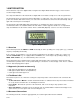
1.0 INT RODUCTION This instrument is a precision digital indicator using the latest Sigma-Delta A/D technology to ensure fast and accurate weight readings. The setup and calibration of the instrument are digital, with a non-volatile security store for all setup parameters. The instrument may be operated from either 4 AA batteries or a DC power source from 12V to 24V. There is a soft power on/off function that retains memory of its state.
Bold Text ^ Bold text denotes words and phrases to note. denotes a Keypad key. Note: In the Specifications section the < symbol means less than and the > symbol means greater than. This symbol denotes one space (used in Automatic Weight Output section 9.1) Items marked with indicate that the setting is available only in Full Setup and is trade critical. When trade critical settings are changed the calibration counter will be incremented. 2.
• • • • • Use connection diagrams to wire up load cell, power and auxiliary cables as required. Use the drill hole template provided for hole locations. Connect Power to indicator and press key to turn the instrument On. Refer to the Setup section 7.0 for information on configuring and calibrating the instrument. To turn instrument Off press and hold key for three seconds (until display blanks). 3.
The DC supply need not be regulated, provided that it is free of excessive electrical noise and sudden transients. The instrument can be operated from a high quality AC wall transformer as long as there is sufficient capacity to drive both it and the load cells. 3.8 Load Cell Connection 3.8.1 Load Cell Signals and Scale Build Very low output scale bases may be used but may induce some instability in the weight readings when used with higher resolutions.
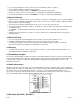
Figure 4: 6-Wire Connections 3.9 Auxiliary Connections This section provides diagrams to illustrate the terminal connections. 3.9.
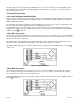
Figure 8: Remote Input 3.9.3 Outputs The output drivers for the instrument are isolated open emitter transistor drives that are capable of driving up to a total of 300mA. This configuration allows for the direct connection of the instrument outputs to most PLC types. The voltage applied to the COM terminal appears on the output lines (i.e. OUT1 and OUT2) when the outputs are active (e.g. to connect to a PLC connect +24V to the common terminal).
A temporary infrared communications link can be established between the instrument and a PC using an optional GSE-LINK cable. The optional GSE-LINK cable can be used to transfer setup and calibration information from a PC (e.g. to be stored for later use and/or transferred to other instruments). It can also be used to download software upgrades to the instrument from a PC. The PC end of the GSE-LINK cable is a standard female DB9 connector.
only. • Caution: Some load cells connect the cable shield directly to the load cell (and therefore the scale base). Connection of the load cell cable shield in this situation may be site specific. 3.12 Regulatory Sealing Requirements To comply with regulatory sealing requirements for each instrument, (i.e. to ensure instruments are not accidentally or deliberately tampered with), it is important that proper sealing procedures be adhered to. Refer to Sealing section 12.2 for more information. 4.
• The currently chosen digit will be flashing. Press to advance to the next digit. • When the digit to edit is flashing, press repeatedly to cycle from 0 through 9. • When the new digit to be set is flashing either press to move to the next digit to edit and repeat the previous step; or press or to accept all of the displayed digits (including the flashing digit) and redisplay the menu item name. 4.
MOTION OVER UNDER ZERO BAND HOLD LOW BATTERY Visible when the displayed reading is not stable. Visible when the setpoint weight is over the setpoint target. Visible when the setpoint weight is under the setpoint target. Visible when the displayed weight is within the zero 'dead' band setting. (The zero band symbol shows near the top right corner of the display.) Visible when the displayed reading is held. Visible when battery voltage is too low and batteries need replacing or recharging.
Note: The key can be locked to prevent the instrument being turned off from the front keypad. Refer to KEY.LOC (Front Panel Key Locking) section 7.4.4 for more information. 5.4.1 Automatic Operation The key on the instrument is unusual in that it has a memory function associated with it. This means that the state of the power setting is remembered even if external power is interrupted.
When leaving the factory, the key is blank and has no primary function preprogrammed. The primary function of this key can be selected from a number of different functions including peak-hold, counting, etc. Refer to Special Functions section 11.0 for details of the available functions. Each primary function has an associated overlay sticker that should be applied to the key to label the function of the key.
Since the instrument uses 5V load cell excitation, the absolute signal voltage is: Calculating the signal resolution: Absolute Signal Voltage = Excitation Voltage x Full Scale Signal = 5V x 1.0mV/V = 5.0mV Signal Resolution = Absolute Signal Voltage Number of Graduations = 5.0mV 1000 divisions = 0.005mV/division = 5µV/division 6.3 Filtering Techniques There is a trade off between noise filtering and the step-response time of the system.
The value(s) of the counter(s) is written on the tamperproof trade label on the front of the indicator for trade-certified applications and functions as an electronic seal. If any legal for trade settings are changed on the instrument, the current value of the calibration counter will be different from the recorded value and the seal is broken. In this manual, items marked with indicate that the setting is legal for trade critical settings. 6.
keys together for two seconds. • The Safe Setup method restricts access to the Trade Critical settings. Changes made in this mode will not increment the calibration counter. In this manual, items marked with indicate that the setting is trade critical. If an attempt is made to enter Safe Setup using the incorrect passcode, or if an attempt is made to alter a trade critical setting while in Safe Setup, the instrument will respond with the message ENTRY DENIED. Refer to Passwords section 6.
key will enter the displayed group, allowing access to the items within the group. The key can be used to cycle through the available items. The key is then used to edit the item. 7.4 Setup Menus The following sections describe the setup parameters of each of the Groups and Items in Setup. 7.4.1 BUILD (Scale Build) Settings within this Group are used to configure the indicator to suit the current application.
used to dampen unwanted weight fluctuations caused by vibrations or dynamic forces. High settings will stabilize the display at the expense of rapid response to sudden weight changes. • Options are: NONE, 0.2, 0.5, 1.0, 2.0, 3.0, 4.0 (time in seconds) • Default: 0.5 (seconds) • MOTION (Motion Detection) Sets how much weight variation over a defined time period is allowed before the displayed weight is deemed to be unstable. This value is displayed as weight change (0.5 or 1.0 graduations) per second.
• CLR.LIN (Clear Linearization Points) Select to view linearization setup and select linearization points to clear. Refer to CLR.LIN (Clear linearization) section 8.3.2 for more information. • DIR.ZER (Direct Zero Calibration) Select to enter the mV/V value of the zero calibration directly. This feature is used to enable approximate calibrations to be performed in situations where a standard ZERO calibration is impractical (e.g. calibration on a partially filled silo). • DIR.
• NONE • TEST • Default: NONE • COUNT • UNITS • HOLD • PEAK.H • LIVE.WT • SHOW.T • AUT.OFF (Auto Power Off / Battery Operation) The instrument can be set up to automatically power down after a period of no activity. Weight motion, network communications or any press of the keyboard is enough to keep the instrument powered on. When operating on batteries the instrument will turn off after 30 minutes of inactivity even if set to NEVER.
• BAUD (Serial Baud Rate) The baud rate determines the serial data transmission speed. Options are: • 2400, 4800, 9600 • Default: 9600 • BITS (Serial Format Options) The Bits options allow the data transmission bit pattern and interface to be changed. The display will show the current setting in the form n81- where each character has a meaning as shown below.
This sets the date format. Options are: • dd.mm.yy • mm.dd.yy • Default: dd.mm.yy • YEAR (Set Year) • Range: 2000 to 2099 • MONTH (Set Month) • Range: 01 to 12 • DAY (Set Day) • Range: 01 to 31 • HOUR (Set Hour) • Range: 00 to 23 (24-hour format) • MINUTE (Set Minute) • Range: 00 to 59 7.4.8 TEST (Special Test Functions) Items within this Group allow access to the testing routines for the instrument. With these routines the scale base output can be monitored and the inputs and outputs can be tested.
configured before calibration is attempted. To perform a calibration, when in Full Setup select the CAL Group using the key. The calibration program will automatically prevent the instrument from being calibrated into an application outside of its specification. If an attempt is made to calibrate outside of the permitted range, an error message will display and the calibration will be abandoned. Refer to Error Messages section 12.4. The instrument has a wide-range ADC.
• When the Span Calibration is complete, press the key to leave the Spanning routine or press , or to re-edit the calibration weight and repeat the operation. 8.2 Performing a Calibration with Direct mV/V Entry In applications where test weights are not easily available, it is possible to calibrate the instrument directly by entering the mV/V signal strength at Zero and full scale Span. The Direct Zero setting (CAL:DIR.ZER) specifies a gross zero point for the scale.
• Press the key to step through the list of points. Each point is shown as Ln.ppp where n is the point number (1 to 5), and ppp is the approximate percentage of full scale where the linearization is applied. For example, L1.050 indicates that linearization point one is active and was entered at about 50% of full scale. Unused linearization points are shown with a row of dashes (e.g. L2. - - -). • Press to change the linearization point selected or press to exit without making any changes.
8.3.2 CLR.LIN (Clear linearization) • Press the key to step through the list of points. Each point is shown as Ln.ppp where n is the point number (1 to 5), and ppp is the approximate percentage of full scale where the linearization is applied. For example, L1.050 designates that linearization point one is active and was entered at about 50% of full scale. Unused linearization points are shown with a row of dashes (e.g. L2. - - -). • Press to choose the linearization point to clear.
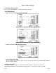
• S2: Displays M/^ representing Motion / Stable, respectively. • S3: Displays Z/^ representing center of Zero / Non-Zero, respectively. • S4: Displays - representing single range. • Printing The instrument has a single fixed printing format that is as follows: 000048 06/05/2003 15:10 121.4 lb G The first line contains a six digit sequential number that is automatically incremented with each printing, up to a maximum of 999999.
10.0 SETPOINTS The instrument is capable of working with two internal setpoints. The status of these setpoints is displayed on the LCD. Each setpoint is associated with a physical output driver but it may also be simply used as an indicator. Refer to SET.PTS (Setpoint Settings) section 7.4.6 for details on settings. 10.1 Setpoint Connection Refer to Auxiliary Connection section 3.9 for the method of connection of the external output drivers. 10.
weight but will not affect any data entry. The following is a sample of a printout displaying kg and lb. 000009 06/05/2003 16:31 2.8 kg G 000010 06/05/2003 16:31 6.1 lb G 11.2.5 HOLD and PEAK HOLD The key implements a manual Hold function. The key implements a Peak Hold function where the largest absolute weight, either positive or negative is stored in the peak value (e.g. -30 is larger than 25). The Hold annunciator is active when the display is showing the held weight.
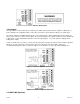
12.0 APPENDIX 12.1 Dimensions Weight Indicator Dimensions in in (mm) (1 inch = 25.4 mm) 3D View Front View Side View Back View Weight Indicator (Desk Mount with Battery Compartment) Dimensions in (mm) (1 inch = 25.4 mm) 3D View Front View Side View Top View CF 147 29 version 1.
12.2 Sealing Details Affix sealing stickers to the rear of the instrument, over one or more screws in the locations indicated. Also affix a sealing sticker over the load cell cable where the cable-tie strain relief is attached, as indicated. Affix stickers in the locations indicated. 12.3 Setup Menu Quick Reference Note: Available only in Full Setup. Changing this setting will increment the Calibration Counter. 1 Available only in Full Setup.
SERIAL SET.PTS CLOCK TEST FACTRY - END - FULL.PC (Full Security Passcode for Digital Setup) KEY.LOC (Front Panel Key Locking) KEY.FN (Key Functions) AUT.OFF (Auto Power Off / Battery Operation) B.LIGHT (Backlight Operation) REM.FN (Remote Function) TYPE (Serial Output Type) BAUD (Serial Baud Rate) BITS (Serial Format Options) ADDRES (Instrument Address) RST.CON (Reset Printed Consecutive Number) SRC (Weight Source) TARG.HI (Target for Overweight) TARG.
(LIN.PT) (LO) 6.6.3 for more information. An attempt has been made to place a linearization point below zero. (PT.TOO) (CLOSE) An attempt has been made to place a calibration point too close to an existing calibration point. (RES) (LO) (RES) (HIGH) (SPAN) (LO) The scale build is configured for less than 100 graduations. The scale build is configured for more than 30,000 graduations. The load cell signal range (span) is too small for these settings.
12.6 Glossary Terms Term Count-by Division EEPROM EMC FIR Full Scale Graduations LED NTEP OIML PLC Range Resolution RFI GSE-LINK Cable RS-232 StepResponse Transients Units Definition The smallest change in weight units that the display can show. See also Resolution. A single graduation. Electrically Erasable Programmable Read-Only Memory Electro-Magnetic Compatibility Regulation Finite Impulse Response The maximum gross weight allowed on the scale.
found and returned as is or merely recalibrated. It may be possible for out-of-warranty products to be returned to the exact original specifications or dimensions. * Technical description of the defect: In order to properly repair a product, it is absolutely necessary for Cooper to receive information specifying the reason the product is being returned. Specific test data, written observations on the failure and the specific corrective action you require are needed. CF 147 34 version 1.