DFI 250 DIGITAL INDICATOR QUICK START MANUAL www.cooperinstruments.
CONTENTS 1.0 INTRODUCTION.................................................................................................................................. 1 1.1 Approvals (for trade versions only) .................................................................................................1 1.2 Manuals ...............................................................................................................................................1 2.0 SHIPPING CONTENTS....................................
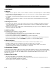
1.0 INTRODUCTION This manual contains information on the installation, calibration and setup of the instrument. 1.1 Approvals (for trade versions only) • NSC approval (4000 divisions at 0.8µV/division). • NMI approval (4000 divisions at 0.8µV/division). • C-tick approved and CE approved. 1.2 Manuals For more information on this instrument refer to the Reference Manual or Quick Start Manual. 2.0 SHIPPING CONTENTS The following table identifies the items shipped with the indicator.
Drive Outputs Battery Backed Clock Calendar 2 isolated transistor drive outputs (300mA total at 50VDC) Battery life 10 years minimum 4.0 WARNINGS 4.1 General • Indicator not to be subject to shock, excessive vibration or extremes of temperature (before or after installation). • Inputs are protected against electrical interference, but excessive levels of electro-magnetic radiation and RFI may affect the accuracy and stability.
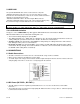
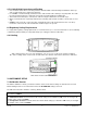
.4 GSE-LINK The optional GSE-LINK cable can be used to transfer setup and calibration information from a PC (e.g. to be stored for later use and/or transferred to other instruments). It can also be used to download software upgrades to the instrument from a PC. • Attach the GSE-LINK cable to the PC using the DB9 connector. • Attach the GSE-LINK head to the left side of the instrument display using the permanent magnet located within the head of the GSE-LINK.
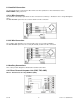
.3 Load Cell Connection The instrument may be connected for either 4-wire or 6-wire operation. For more information, refer to BUILD:CABLE setting section 7.6. 6.3.1 4-Wire Connection The minimum connectivity requirements are the connection of four wires (i.e. Excitation + and – along with Signal + and –). The BUILD:CABLE option must be set to 4 to allow for 4-wire connection. 6.3.2 6-Wire Connection The excitation and signal lines are connected the same as for a 4-wire installation.
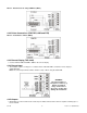
RS-232 - Instrument to PC using COM Port (DB25) 6.4.2 Printer Connections (RXD/TXD, GND and DTR) RS-232 – Instrument to Printer (DB25) 6.4.3 Remote Display (TXD, GND) • Connect TXD to RXD and GND to GND on the remote display. 6.4.4 Remote Input • The indicator requires a voltage free contact between TXD and RXD to enable the remote input (i.e. SPEC:REM.FN). Note: The remote input will not function when in setup or when using the GSE-LINK. WARNING The remote input is a voltage free contact (e.g.
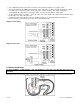
• This configuration allows for the direct connection of the instrument outputs to most types of PLC. • The voltage applied to the COM terminal appears on the output lines (i.e. OUT1 and OUT2) when the outputs are active (e.g. to connect to a PLC connect +24V to the common terminal). The outputs can then be connected directly to PLC inputs so when the outputs are active the PLC will see a 24V signal. • To drive external loads (e.g.
6.5.1 Cable Shield Connection and Earthing • Care should be taken when connecting shields to maximize EMC or RFI immunity and minimize earth loops and crosstalk (interference) between instruments. • For full EMC or for RFI immunity, termination of the cable shields at the earth lug is very important. The earth lug of the instrument must be separately connected to ground potential via a reliable link. • The instrument should only be connected to earth via a single reliable link to avoid earth loops.
7.1.1 Trade Critical Settings Trade critical settings can affect calibration and/or legal for trade performance. In this document the symbol indicates the setting is trade critical. Each time a trade critical setting is altered, the calibration counter will be incremented by one. 7.2 GSE-LINK For information on setting up using the GSE-LINK cable refer to GSE-LINK section 5.4. 7.3 Access Full Setup Full Setup provides access to configure and calibrate the instrument.
GROUP (GRP) BUILD OPTION CAL CF 146 ITEM (ITM) SELECT (SEL) EDIT (EDT) OK Underline = Defaults 000000, 00000.0, 0000.00, 000.000, 00.0000, 0.00000 000100 to 999999 Default = 003000 changes position, changes digit. 1, 2, 5, 10, 20, 50, 100 none, g, kg, lb, t OFF, ON 4, 6 INDUST, OIML, NTEP none, 0.2, 0.5, 1.0, 2.0, 3.0, 4.0 DP CAP Decimal Point Position Maximum Capacity RES UNITS HI.
SPEC DIR.ZER (L1, L2, L3, L4, L5) Direct Zero Calibration (Current weight displays) DIR.SPN Direct Span Calibration (Current weight displays) FAC.CAL SAFE.PC Factory Calibration Cont. N (No) Cont. Y (Yes) Safe Setup Passcode FULL.PC Full Setup Passcode KEY.LOC Front Panel Key Locking P12345 (P for Power key. Other keys numbered from the left, ie. Zero=1.) Key Setting Auto Power Off / Battery Operation KEY.FN AUT.OFF SERIAL SET.PTS CF 146 B.LIGHT Backlight Operation REM.
TARG.HI FORMAT YEAR Target for Overweight Setpoint 1 (Output 1) Target for Underweight Setpoint 2 (Output 2) Date Format Setting Year Setting MONTH Month Setting DAY Day Setting HOUR Hour Setting MINUTE Minute Setting SCALE Scale Base Test Display FRC.OUT Force Outputs FACTRY DEFLT - END - EXIT SETUP Restore Factory Defaults Cont. N (No) Cont. Y (Yes) Save settings and return to normal weighing mode TARG.
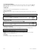
8.0 ERROR MESSAGES 8.1 Weighing Errors • Check Setup = This item can be checked on site by service personnel. Error (U - - - - -) Description The weight is below the minimum allowable weight reading. (O - - - - -) The weight is above the maximum allowable weight reading. Warning – overloading may damage mechanical scale elements. (ZERO) (ERROR) The weight reading is beyond the limit set for Zero operation. The operation of the key is limited in the setup during installation.
(E0100) (E0200) (E0300) (E0400) (E0800) (E2000) (E4000) (E8000) too low or too high. The digital setup information has been lost. The calibration information has been lost. All setup information has been lost The factory information has been lost. The EEPROM memory storage chip has failed ADC Out of Range Error. This may be caused from a broken load cell cable. The battery backed RAM data has lost data.