DFI 200 HAND HELD INDICATOR OPERATION MANUAL 1 INTRODUCTION This manual contains information for the operation of the DFI 200 hand held load cell monitor. The DFI 200 is suitable for measuring weight, pressure, force, torque etc. The input required by the DFI 200 is a 4 wire mV/V output type transducer. 5V excitation is provided for the transducer. Calibration, and set up functions are easily achieved via front pushbuttons. The DFI 200 is a high accuracy meter with the capability of high speed sampling.
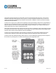
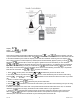
ELECTRICAL CONNECTIONS Power for the DFI 200 is provided by a 9VDC (216) battery. The battery cover is located at the underside of the case. External connections to the DFI 200 are made via a 9 pin “D” male connector. The DFI 200 provides 5VDC excitation for the mV/V output transducer. Electrical connections are as shown below. Refer to ”External memory” chapter for details of the optional external memory chip. Refer to ”Serial Communications” chapter for details of the RS232 wiring connections.
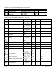
FUNCTION TABLES – SUMMARY OF SETUP FUNCTIONS Functions in this first table are available in FUNC or CAL mode. Display Function Calibration memory selection Display rounding Memory chip address Decimal point place Digital filter Range , to to to to Default , Your record or Ref 4.1 4.2 4.3 4.4 4.5 Functions in this second table are available only in CAL mode. Display Function Range Default Ref mV/V input range 4.6 Sample rate in samples/sec. 4.7 User pushbutton function 4.
EXPLANATION OF FUNCTIONS The DFI 200 setup and calibration functions are configured through a push button sequence. Two levels of access are provided for setting up and calibrating namely: • mode (simple push button sequence) allows access to calibration channel selection, display rounding, decimal point and digital filter settings only. • mode (power up sequence plus push button sequence) allows access to all functions including calibration parameters.
scaling values may be entered for a single cell, allowing the same cell to display in different units e.g. Kilonewtons, Kilograms and Tons. The user may select the load cell to be used via this function or via the User pushbutton if the pushbutton has been programmed for this purpose (see function). To scale any of these and methods or independent calibration memories you may use either the method.
Default Value: Displays and sets the decimal point place. By pressing the or be set. The display will indicate as follows: (no decimal point), (3 decimal point places). decimal point places) or pushbuttons the decimal point position may (1 decimal point place), (2 4.5 Digital filter Display: Range: to Default Value: Displays and sets the digital filter value.
measurement mode. Any changes to the function selected when the button was pressed will not be saved. This function may be set to any one of the following: • • - Button has no special function. (Push button tare) - the pushbutton must be pressed for 2-3 seconds to perform a tare operation. When tare is selected you can toggle between the nett, tare and gross displays via the User pushbutton. The message • , or will precede the measurement value.
9. The display will now indicate (2nd calibration point). If you do not wish to enter the second point at this message is seen. If you wish to enter the second stage then press and release the F button until the and buttons simultaneously. point at this stage press the (2nd calibration point) followed by a “live” reading. 10. The display will now indicate 11. Apply an input of 100% (again this value is not critical, but there must be at least 10% of rated capacity difference between and inputs.
4.11 Alternative mV/V calibration method Display: Range: Default Value: This function provides an alternative calibration method to the and method of scaling, note that method allows the known rated mV/V value of the load cell only one of these methods should be used. The to be entered followed by the maximum capacity of the load cell in whatever measuring units are required. The ). mV/V value is entered to 3 decimal places (3 decimal places will automatically appear up when you enter value is 9.999.
Use of and as reference values. Note: do not use this facility if an optional external memory chip is connected. If using the two point calibration and ) the mV/V value and scale is automatically calculated and stored at the and method ( functions. After calibration using and the and values may be viewed and a or values whilst they are being note taken of their value, ensure that you do not change either the and values recorded can be reviewed.
Note that the zero operation is cumulative i.e. the zero operations are added in memory. For example if the display is scaled to read from 0 to 1000 and the zero range is set at 20.0% then the DFI 200 will allow multiple zero operations up until a total 200 (20% of 1000 = 200) units have been zeroed off.
Default Value: Power off time - selects the automatic power off time in minutes. This function allows the instrument to conserve battery power by automatically powering down if a button has not been pressed for the number of minutes selected. Selections allow range from 0 to 300 minutes. If 0 minutes is selected then the instrument will not automatically power down and must be switched off via the On Off pushbutton. 4.
function characters (such as and ). Therefore 32 (DEC) or 20 (HEX) is address 0, 42 (DEC) or 2A (HEX) is address 10. Refer to chapter 6 for further details. 4.22 Returning to normal measure mode When the calibration has been completed it is advisable to return the instrument to the normal mode (where calibration functions are less likely to be tampered with). To return to normal mode, turn off power to the instrument, wait a few seconds and then restore power. 4.
Note: each external memory device should be allocated a unit address, see function. Valid addresses are 1 to 250. If the Unit function indicates an address of 255 then this indicates that the memory device has not been given an address. The same address can be allocated to more than one memory device and the address of a device can be changed at any time. The setting of individual unit addresses simply allows identification of the load cell by viewing the Unit function.
6 SERIAL COMMUNICATIONS 6.1 DIP switch settings The RS232 communications can be enabled or disabled via a DIP switch SW7 located at the display end of the DFI 200 circuit board. Switch 3 of this DIP switch is used to switch the communications facility on or off as detailed below. To gain access to the DIP switch remove the four screws at the rear of the DFI 200 case and remove the back. The back is connected to the circuit board via a ribbon cable; there is no need to unplug this cable.
6.3 Serial communications function settings and commands With the communications enabled the following extra functions will be seen, these function should be set to match the settings on the PC or other device which the DFI 200 is communicating with. (set baud rate) Select from or baud. (set parity) Select parity check bit to either CF 112 . 16 Version 3.
(set RS232/485 interface mode) Select interface operation as follows:- or . Allows user to select the RS232/485 - Sends image data from the display without conversion to ASCII. This mode is intended for use • only when the DFI 200 is used to transmit data to a compatible display. - Sends ASCII form of display data every time display is updated. • - Controlled by computer or PLC as host. Host sends command via RS232 and the instrument • responds as requested in ASCII form.
A typical format for the host command is:- CA (Standard read) Where: is Start of Text Character (2 Dec, 02 Hex, ^B ASCII) C is the command character (see following commands) A is the unit address (Range: 32 to 63 Dec, 20 to 3F Hex, “SPACE” to ? ASCII, the address is offset by 32 Dec, 20 Hex) is Carriage Return (13 Dec, 0D Hex, ^M ASCII) The commands available and instrument responses are as follows: 1. Transmit Primary Display Value: PA e.g.
4. Invalid Command. If the command received from the host is not valid then the unit may return the following:?A Where: is Acknowledge (6 Dec, 06 Hex) ? is the character “?” (63 Dec, 3F Hex) A is the responding units address is a Carriage Return (13 Dec, 0D Hex) If the address received from the host does not match the units address then the unit will not respond at all. 7 SPECIFICATIONS 7.
Note: Figures in the table above apply when the digital filter setting is 0. Add 0.5 bits effective resolution for each step on the digital filter setting e.g. if the digital filter is set at 4 add 2 bits of effective resolution to each of the figures in the table above. Resolution in μV can be calculated using the resolution in bits figures above. These μV resolution values are calculated by the following method: Resolution (μV) = full signal input voltage range / number of divisions of resolution. e.g.
found and returned as is or merely recalibrated. It may be possible for out-of-warranty products to be returned to the exact original specifications or dimensions. * Technical description of the defect: In order to properly repair a product, it is absolutely necessary for Cooper to receive information specifying the reason the product is being returned. Specific test data, written observations on the failure and the specific corrective action you require are needed. CF 112 21 Version 3.