DFI 1650 COMMUNICATIONS GUIDE
Table of Contents Chapter 1 Introduction................................................................................................................................... 1 1.1 About This Manual............................................................................................................................... 1 1.1.1 Scope............................................................................................................................................ 1 1.1.2 Conventions ...............
6.4 QBasic I QuickBasic .......................................................................................................................... 12 6.5 Visual BASIC 5 or 6........................................................................................................................... 12 6.5.1 MSCOMM Active X Control ........................................................................................................ 12 6.5.2 Third party Active X controls and DLLs .............................
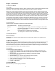
Chapter 1 Introduction 1.1 About This Manual 1.1.1 Scope This manual contains information about the wiring and protocol used for serial communications SC series instruments. This series includes the models DFI 1650, DFI 1650PT, and DFI 1650-3004. Nearly all of the DFI’s features available via its front panel switches, indicators, display and rear panel connectors are also available through its serial communications interface.
• • • • DFI 1550: 1 to 4 physical channels, 3/8 DIN case, no limits or peak detector DFI 1650: 1 to 4 physical channels, 3/8 DIN case DFI 1650PT: 1 to 4 physical channels, portable case DFI 1650-3004: 1 to 14 physical channels, 19" rack mount case, 1 to 3 quad-Iine displays 1.3.3 Channel Types Channels can be one of three types: Input, Output, or Virtual Input Channels Input channels are hardware circuit boards with a unique channel number.
• • • • • • • • Full-scale mV/V: The full-scale millivolt-per-volt (mV/V) rating of the transducer when its full load is applied; also called "calibration factor". Shunt-Cal mV/V: The millivolt-per-volt output of the transducer when the shunt calibration resistor is placed across its -SIGNAL and -EXCITATION leads. Shunt Resistance: The resistance value, in Ohms, that was used to obtain the shunt-cal mV/V value above. Full-Scale Value: The full-scale value of the transducer, in engineering units.
The instrument enters its INITIALIZE mode that lasts a few seconds per channel. When the instrument enters its normal operating mode (RUN mode), you will see the following format on the front panel display: 1 c ØØØØØ. PSIG ◊ 2.5 Configure a Terminal Emulator Program Start your favorite terminal emulator program. Configure it to communicate with the serial port you have connected the instrument to (usually COM1 or COM2), at 9600 baud, no parity bits, 8 data bits and 1 stop bits ("9600,8,N, 1").
relating to this functionality will not work with it. If a command is not available on such an instrument, it will be mentioned in the description for that command. Likewise, if your instrument is not equipped with an optional Relay/DAC channel, commands relating to relays and DAC outputs will not work on your instrument. 3.4 Two Types of Commands 3.4.1 System Commands System commands are commands that apply to the entire instrument.
3.6.2 Command Codes The first character of each two-character command code signifies if that command is a function command ("F"), a read operating parameter command ("R"), or a write operating parameter command ("W"). Read and write commands can be used instead of the front panel setup menus to configure the operation of the instrument. Function commands are used as an alternative to the front panel to gather data from the instrument or to cause it to perform an operation. 3.6.
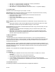
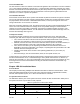
6 7 8 20 22 pin 4) RS-232 Data Set Ready Output 7 RS-232/RS-485 reference Reference RS-232 Data Carrier Detect (not N/A N/A connected) DTR RS-232 Data Terminal Ready (not N/A N/C connected) RI RS-232 Ring Indicator (not connected) N/A N/C The RS-232 communications pins are electrically isolated from the rest of the instrument. The RS-232 and RS-485 interfaces are exclusive; an instrument cannot have both. DSR GND DCD 4.
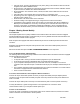
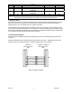
Model DFI DB-25 connector DCE Computer or Terminal DB-9 connector DTE Figure 4-2: Wiring to 9-pin DTE Chapter 5 RS422/RS-485 Installation Notes 5.1 Introduction This chapter provides wiring examples and hardware information for RS-422/RS-485 communications. "Bus master" will be used to refer to the personal computer, programmable controller, terminal, data acquisition system, etc. to which the instrument is connected. 5.
The RS-485 communications pins are electrically isolated from the rest of the instrument. The RS-232 and RS-485 interfaces are exclusive; an instrument cannot have both. 5.4 RS-422 Wiring RS-422 uses two pairs of wires to communicate between one bus master and up to 10 slave devices. It is a full-duplex system, i.e. the bus master can transmit and receive data from the slaves at the same time.
5.6.1 Determine Address To determine what address the instrument is using from the front panel: 1) Enter the setup menus by pressing [UP] and [DOWN] together. The display will read “SETUP” and then “CHANNEL 01 MENU” (which is the top-most item on the setup menus). 2) Press and release [DOWN] until the display reads “SERIAL COM.MENU”. Press [ENTER] to enter the SERIAL COM. menu. 3) Press and release [DOWN] until the display reads “ADDRESS".
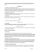
Next, select the serial port you wish to connect with. Finally, configure the serial port parameters as shown below.
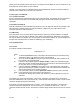
If HyperTerminal reports "Unable to open Com 2" (or whatever port you are using} some other application on your computer is currently using the port. It could be a printer, a mouse or another terminal emulation program. 6.2.3 Establish Communications Type “#00RR” (you will not see these characters on the screen) then press enter to transmit this command to the instrument. If all goes well, the instrument should respond with a message in the form of “084-1500-01 2.07”. 6.3 WinWedge WinWedge (a.k.a.
6.5.2 Third party Active X controls and DLLs Because of the above problems with the MsComm control, you may wish to use a third-party Active X control for serial communications. One such product is CommX from Greenleaf software. Their web site is located at: http://www.greenleafsoftware.com Several vendors offer DLL libraries for serial communications. MarshallSoft Computing offers 16-bit and 32-bit DLLs available as a shareware download. Their web site is: http://www.marshallsoft.com 6.6 C and C++ 6.6.
"CommLib" and "CommX" are trademarks of Greenleaf Software Inc. "National Instruments" and "LabVIEW" are trademarks of National Instruments Corporation. "MARSHALLSOFT" is a registered trademark of MarshallSoft Computing, Inc. Chapter 7 System Commands 7.1 Introduction System commands affect the operation of the entire instrument. 7.2 Listings Following are the Commands listed in this section.
Example Reply If “#00F6↵“ is sent when limits 02 and 04 are activated, the reply will be “10.” The floating-point value in the reply is created by adding together the values for each activated limit as shown below. Limit number Value 01 1. 02 2. 03 4. 04 8. 05 16. 06 32. 07 64. 08 128. 09 256. 10 512. 11 1024. 12 2048. 13 4096. 14 8192. 15 16384. 16 32768. This command does not apply to instruments not equipped with limits, such as the DFI 1550.
FL Transmit Multiple Readings Purpose Usage Transmit a set of multiple readings as defined with the "WL" command #aaFL↵” # is the 'pound' or 'hash' character (ASCII decimal 35). aa is the two-character instrument address. ↵ is the 'carriage return' character (ASCII decimal 13). Suppose that the command “#00WL01110212↵“ has been previously sent. Sending “#00FL↵“ might result in a reply of “-001.2, 0051.3, 000.05, 100.
Example Reply aa is the two-character instrument address. n is the argument defined below. ↵ is the 'carriage return' character (ASCII decimal 13). “0” disables the auto line-feed function. Each reply ends only with a carriage return. “1” enables the auto line-feed function (default). Each reply ends with a line-feed/carriagereturn combination. “#00W20↵” “OK” or “ERROR” W4 Write Address Purpose Usage Writes a new baud rate for serial communications "#aaW4nn.
Example Reply Remarks Sending “00WB04415.5↵“ will change the RETURN POINT of Limit 4 to 415.5. When writing: "OK", "ERROR" or "N/A" When reading: an floating-point value or "N/A" This command does not apply to instruments not equipped with limits, such as the DFI 1550. RC/WC Read/write Limit Operation Purpose Usage Argument Reads or writes the operation of a limit. “#aaRCpp↵” to read, “#aaWCppn↵” to write. # is the 'pound' or 'hash' character (ASCII decimal 35).
Argument Examples Reply Remarks aa is the two-character instrument address. n is the argument defined below. ↵ is the 'carriage return' character (ASCII decimal 13). "0" disables continuous transmission (default). The instrument will only transmit when requested. "1" enables continuous transmission of the front panel display. This is equivalent to sending the system command "F0 Transmit Front Panel Display" repeatedly. The instrument will respond to other commands normally.
Reply Remarks RP/WP Purpose Usage Parameters& Arguments reply with the track, peak and valley values of channel 03. The instrument will reply with "OK". When writing: "OK", "ERROR" or "N/A". When reading: a list of hexadecimal characters as explained above. See "FL Transmit Multiple Readings" and "WI Write Continuous Transmit Setting" for more information. Read/write Dual-Line Display Operation Read or Write the operation of the dual-Iine display “#aaRPpp↵” to read, “#aaWPppn↵” to write.
Example Reply Remarks 11 11. 12 12. 13 13. 14 14. 15 15. 16 64. 17 65. 18 66. 19 67. 20 68. 21 69. 22 70. 23 71. If the instrument is setup to display channel 01 's track value on power up, sending “#00RQ↵” will generate a reply of "1". When writing: “OK" or "ERROR". When reading: a number corresponding to a channel number and data value as shown above. See also "RS/WS Read/Write Channel to Display".
Examples Reply Remarks 12 12. 13 13. 14 14. 15 15. 16 64. 17 65. 18 66. 19 67. 20 68. 21 69. 22 70. 23 71. Sending “#00WS01↵” will cause the display to show channel 01 's tracking value. The instrument will reply with "OK". Sending “#00WSUP↵” will increment the channel number shown on the display. The instrument will reply with "OK". When writing: "OK" or "ERROR". When reading: a numeric value corresponding to a channel number and data value as explained above.
Reply A list card types, followed by a CRC check. The list of card types consists of a series of two hexadecimal - characters for every installed channel in the instrument. Note that the display is considered to be an installed channel with a channel number of "00". The CRC check consists of four hexadecimal characters, which is the 16-bit Cyclic Redundancy Check of the ASCII characters 8 in the reply. The polynomial used is Remarks This command is intended for internal factory use.
F5 Apply Shunt Resistor and Transmit Reading Purpose Usage To apply the channel's internal shunt resistor to the transducer and transmit a reading. “#aaccF5↵” # is the 'pound' or 'hash' character (ASCII decimal 35). aa is the two-character instrument address. cc is the two-character channel number ↵ is the 'carriage return' character (ASCII decimal 13).
FF Transmit Analog-to-Digital Converter Reading Purpose Example Reply Remarks To transmit the Analog-to-Digital converter reading as a percentage from -100% to +100% of the AID converter’s full scale “#aaccFF↵” # is the 'pound' or 'hash' character (ASCII decimal 35). aa is the two-character instrument address. cc is the two-character channel number ↵ is the 'carriage return' character (ASCII decimal 13 ).
R7/W7 Read/write Full-Scale Range Purpose Usage Reads or writes the channel's "FULL SCALE MU/U" menu item “ #aaccR7↵” to read, “#aaccW7n↵” to write # is the 'pound' or 'hash' character (ASCII decimal 35). aa is the two-character instrument address. cc is the two-character channel number n is the full-scale mV/V value. ↵ is the 'carriage return' character (ASCII decimal 13). “#0001W73.2↵” When writing: "OK" or "ERROR". When reading: an ASCll-floating-point value.
Example Reply "03" accesses the "KNOWN POINT 4/5" menu item. "04" accesses the "KNOWN POINT 2/2", "KNOWN POINT 3/3" or "KNOWN POINT 5/5" menu items. “#0001RK01↵” When writing: "OK" or "ERROR". When reading: an ASCll-floating-point value. Changing this value has no effect until the channel is re-calibrated to the transducer with the Known-Load Calibration method. RM/WM Read/Write DAC Channel & Value Purpose Usage Reads or writes the channel's "DAC. CHANNEL" and "DAC.
Example Reply “#0001WN-8000↵” When writing: "OK" or "ERROR". When reading: an ASCll-floating-point value. RO/WO Read/Write DAC Full-Scale Value Purpose Usage Reads or writes the channel's "DAC. FULL-SCALE" menu item “#aaccRO↵” to read, “#aaccWOn↵” to write # is the 'pound' or 'hash' character (ASCII decimal 35) aa is the two-character instrument address cc is the two-character channel number ~ n is the full Analog Output value in engineering units. z ..
When reading: a numeric value according to the information above. RQ/WQ Purpose Usage Argument Read/Write Display Formatting Reads or writes the operation of the channel's display formatting. “#aaccRQ↵” to read, “#aaccWQn↵” to write. # is the 'pound' or 'hash' character (ASCII decimal 35). aa is the two-character instrument address. cc is the two-character channel number n is the argument defined below. ↵ is the 'carriage return' character (ASCII decimal 13).
Argument n is the argument defined below. ↵ is the 'carriage return' character (ASCII decimal 13) The argument is created by adding together the values of the desired options as shown. [VALUE] ENABLED DISABLED Example Reply Remarks Value 0. 8. [CLEAR] ENABLED DISABLED Value 0. 4. [CHANNEL] Value ENABLED 0. DISABLED 2. [TARE] ENABLED DISABLED Value 0. 1. It is desired to disable the [TARE] button for channel 02 when the Protection jumper is installed. Sending “#0002WT1↵“ will accomplish this.
Example Reply F2 Purpose Usage Example Reply F9 Purpose Usage Example Reply Remarks FA Purpose Usage Example Reply Remarks FB Purpose Usage Example Reply Remarks FF Purpose Usage Example CF 126 ↵ is the 'carriage return' character (ASCII decimal 13). “0001F1↵" "OK" Deactivate Tare To remove the offset from the channel's data values that was applied when tare was activated. "#aaccF2↵" # is the 'pound' or 'hash' character (ASCII decimal 35). aa is the two-character instrument address.
Reply Remarks “872945" (typical) none FH Purpose Usage Write DAC Control Value To control the channel's Digital-to-Analog Converter (DAC) manually or automatically. "#aaccFHn↵" # is the 'pound' or 'hash' character (ASCII decimal 35). aa is the two-character instrument address cc is the two-character channel number n is the argument defined below. ↵ is the 'carriage return' character (ASCII decimal 13). "AUTO" returns the DAC to its normal automatic operation (power-on default).
Example Reply "#0001W7l0. ↵" When writing: "OK" or "ERROR". When reading: an ASCll-floating-point value. Changing this value will change the gain of the amplifier circuit. It is recommended that a re-calibration of the transducer to the channel be performed to maintain calibration. RK/WK Purpose Usage Read/Write Known-Load Calibration Point Reads or writes the channel's "KNOWN POINT x/y" menu items "#aaccRKpp↵" to read, "#aaccWKppn↵" to write. # is the 'pound' or 'hash' character (ASCII decimal 35).
Example Reply Remarks RN/WN Purpose Usage Example Reply RO/WO Purpose Usage Example Reply RP/WP Purpose Usage Parameters & Arguments 19 67. 20 68. 21 69. 22 70. 23 71. “aaccRM33↵” will cause the channel 01's DAC to monitor channel 01 's valley value. When writing: "OK", "ERROR" or "N/A". When reading: a number corresponding to a channel number and data value as shown above. none Read/write DAC Zero-Scale Value Reads or writes the channel's "DAC.
Using pp="02" accesses the "AUX1 FUNCTION" menu item. Using pp="03" accesses the "AUX2 FUNCTION" menu item. Example Reply RQ/WQ Purpose Usage Argument Example Reply RR Purpose Usage Example CF 126 When writing these parameters: n=0 means the Auxiliary Function pin is disabled. n=1 means track hold. n=2 means peak & valley hold. n=4 means peak & valley clear (edge triggered) n=16 means activate Tare function. n=32 means deactivate Tare function.
Reply Remarks RT/WT Purpose Usage Argument A text string such as 084-1169-0101 This is the part number and version of the firmware used by the channel's microprocessor. Read/write Front Panel Switch Operation Reads or writes the operation the front panel switches when the Protection jumper is installed. "#aaccRT↵" to read, "#aaccWTn↵" to write. # is the 'pound' or 'hash' character (ASCII decimal 35). aa is the two-character instrument address. cc is the two-character channel number.
Example Reply Remarks “#0001F0↵" “5670.5" (typical) The input channel continuously reads the transducer. This function transmits the most recent reading. F1 Purpose Usage Activate Tare To reset the channel's data values to zero “#aaccF1↵" # is the 'pound' or 'hash' character (ASCII decimal 35). aa is the two-character instrument address. cc is the two-character channel number ↵ is the 'carriage return' character (ASCII decimal 13).
Remarks This command is not available on the DFI 1550. FB Purpose Usage Clear Peak and Valley Data To reset the channel's peak and valley data values to the track value. "#aaccFB↵" # is the 'pound' or 'hash' character (ASCII decimal 35). aa is the two-character instrument address. cc is the two-character channel number ↵ is the 'carriage return' character (ASCII decimal 13). "#0001FB↵" "OK" or "N/A" This command is not available on the DFI 1550.
R6/W6 Purpose Usage Example Reply R7/W7 Purpose Usage Argument Example Reply R8/W8 Purpose Usage Example Reply R9 Purpose Usage Argument Example Reply CF 126 Read/write Units Label Reads or writes the channel's "DISPLAY. UNITS" menu item "#aaccR6↵" to read, "#aaccW6n↵" to write. # is the 'pound' or 'hash' character (ASCII decimal 35). aa is the two-character instrument address. cc is the two-character channel number n is the four-character units label.
A value of 3 means the Signal Type Jumper is set to "voltage". A value of 4 means the Signal Type Jumper is set to "current". RK/WK Purpose Usage Parameter Example Reply RM/WM Purpose Usage Argument Read/write Known-Load Calibration Point Reads or writes the channel's "KNOWN POINT x/y" menu items "#aaccRKpp↵ " to read, "#aaccWKppn↵" to write. # is the 'pound' or 'hash' character (ASCII decimal 35). aa is the two-character instrument address.
23 Example Reply Remarks RN/WN Purpose Usage Example Reply RO/WO Purpose Usage Example Reply RP/WP Purpose Usage Parameters 71. "#0001RM33↵" will cause the channel 01's DAC to monitor 8 channel 01 's valley value. When writing: "OK", "ERROR" or "N/A". When reading a number corresponding to a channel number and data value as shown above. none Read/write DAC Zero-Scale Value Reads or writes the channel's “DAC. ZERO-SCALE" menu item "#aaccRN↵" to read, "#aaccWNn↵" to write.
Using pp="01" accesses the "CALIBRATION TYPE" menu item. When writing this parameter: n=1 means Shunt Calibration. n=2 means 2-Point Known-Load Calibration. n=3 means 3-Point Known-Load Calibration. n=5 means 5-Point Known-Load Calibration. Using pp="02" accesses the "AUX1 FUNCTION" menu item. Using pp="03" accesses the "AUX2 FUNCTION" menu item. Example Reply RQ/WQ Purpose Usage Argument When writing these parameters: n=0 means the Auxiliary Function pin is disabled. n=1 means track hold.
Usage Example Reply Remarks RT/WT Purpose Usage Argument "#aaccRR↵" # is the 'pound' or 'hash' character (ASCII decimal 35). aa is the two-character instrument address. cc is the two-character channel number ↵ is the 'carriage return' character (ASCII decimal 13). "#0001RR↵" A text string such as 084-1169-01 01 This is the part number and version of the firmware used by the channel's microprocessor.
11.2 Descriptions F0 Transmit Track Data Purpose To maintain compatibility with other types of channels Usage #aaccF0↵” # is the 'pound' or 'hash' character (ASCII decimal 35). aa is the two-character instrument address. cc is the two-character channel number ↵ is the 'carriage return' character (ASCII decimal 13). Example “#0002F0↵” Reply “ 00000." Remarks Since this channel generates no track, peak or valley data values, this command always returns 0.
Example Reply "#0012FJ12↵" turns on relays 3 and 4 of channel 12 "OK" or "ERROR" RA/WA Purpose Usage Read/write Limit Set Point Reads or writes the SET POINT of a limit "#aaRApp↵ " to read, "#aaWAppn↵" to write. # is the 'pound' or 'hash' character (ASCII decimal 35). aa is the two-character instrument address. pp is the two-numeric-character limit number. n is the limit SET POINT value. ↵ is the 'carriage return' character (ASCII decimal 13). Sending "#00WA01325 .
Example Reply Remarks 17 4352. Energize Value 18 4608. signalsetpoint 16. 20 5120. signal inside 32. 21 5376. signal outside 48. 22 5632. 23 5888. It is desired to have Limit 1 to operate as follows: Limit will monitor channel 01 = 256 Source of limit is track value =0 Enable limit operation =1 Do not latch limit after it activates =0 Activate when signal > setpoint = 16 Sending "#00WC01273↵" will change Limit 1 operation accordingly. When writing: "OK", "ERROR" or "N/A".
Reply Remarks " 00000." Since this channel generates no track, peak or valley data values, this command always returns 0. This command is not available on the DFI 1550. FH Write DAC Control Value Purpose Usage To control the channel's Digital-to-Analog Converter (DAC) manually or automatically. "#aaccFHn↵" # is the 'pound' or 'hash' character (ASCII decimal 35). aa is the two-character instrument address. cc is the two-character channel number n is the argument defined below.
When reading: an number corresponding to a channel number and data value as shown above. RN/WN Read/Write DAC Zero-Scale Value Purpose Usage Reads or writes the channel’s “DAC.ZERO-SCALE” menu item. “#aaccRN↵” to read, “#aaccWNn↵” to write # is the ‘pound’ or ‘hash’ character (ASCII decimal 35). aa is the two-character instrument address. cc is the two-character channel number. n is the zero Analog Output value in engineering units. ↵ is the ’carriage return’ character (ASCII decimal 13).
returns 0. This command is not available on the DFI 1550. FA Transmit Valley Data Purpose Usage To maintain compatibility with other types of channels “#aaccFA↵" # is the 'pound' or 'hash' character (ASCII decimal 35). aa is the two-character instrument address. cc is the two-character channel number ↵ is the 'carriage return' character (ASCII decimal 13). 1I#0002FA↵" “ 00000." Since this channel generates no track, peak or valley data values, this command always returns 0.
Chapter 14 Mathematics Virtual Channel Commands 14.1 Introduction These commands affect the operation of Mathematics Virtual channels. 14.2 Descriptions FO Transmit Track Data Purpose Usage To transmit the channel's tracking data value "#aaccFO↵" # is the 'pound' or 'hash' character (ASCII decimal 35). aa is the two-character instrument address. cc is the two-character channel number . ↵ is the 'carriage return' character (ASCII decimal 13). "#0001FO↵" " 5670.
Example Reply Remarks ↵ is the 'carriage return' character (ASCII decimal 13). "#0001FA↵” "-0012.5" (typical) or "N/A" This command is not available on the DFI 1550. FB Clear Peak and Valley Data Purpose Usage To reset the channel's peak and valley data values to the track value "#aaccFB.J" # is the 'pound' or 'hash' character (ASCII decimal 35). aa is the two-character instrument address. cc is the two-character channel number ↵ is the 'carriage return' character (ASCII decimal 13).
Reply 5 digit, bipolar display =0 Count by one digit =0 Enable display averaging = 64 Sending "#000BWQ66↵" will change display operation accordingly. When writing: "OK" or "ERROR". When reading: an ASCll-floating-point value described above. RT/WT Read/write Front Panel Switch Operation Purpose Reads or writes the operation the front panel switches when the Protection jumper is installed. "#aaccRT↵" to read, "#aaccwTn. ↵" to write. # is the 'pound' or 'hash' character (ASCII decimal 35).
Advance authorization is required prior to the return to COOPER. Before returning the item contact the Repair Department at (540) 349-4746 to obtain a Return Material Authorization. Shipment to COOPER shall be at buyer’s expense and repaired or replacement items will be shipped F.O.B. our plant in Warrenton, Virginia. Non-verified problems or defects may be subject to a $125 evaluation charge. Please return the original calibration data with the unit.