
Manual

CF 66 46 Rev. C 2/05
The analog-to-digital converter input circuit features adjustable digital, low-pass filtering, 12- to 18-bit resolution
(depending on the filter setting) and has several different input ranges. These many ranges allow ±50,000 count
resolution (at the slowest filter setting) across a wide variety of input ranges.
A combination of SETUP menu items and hardware jumpers are used to configure the excitation supply out put
voltage (+28 VDC, ±15 VDC, +15 VDC or +12 VDC), the input type (voltage or current) and input reference
(differential or single ended).
Two methods of calibrating the High-Level Input channel to the transducer are available: known-load calibration
and shunt calibration. The benefits of each are discussed in “CALIBRATON TYPE menu Item” in Chapter 12.
Two rear panel control inputs can be field-configured for such functions s remote tare, disabling peak/valley
detection and clearing the peak/valley values. A voltage or current digital-to-analog output is also provided.
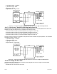
12.2 Wiring
12.2.1 Channel Connector
Connect the amplified transducer, in-line amplifier or DC-DC LVDT to a High-Level Input channel by wiring it to the
12-pin connector of that channel. The System Calibration Sheet that shipped with the instrument describes which
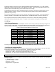
cards are installed in each channel. The pin-out for this connector is shown on the following table.
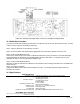
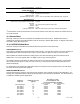
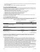
Table 12-1: High-Level Input Channel Pin Connections
Pin Label Function Reference Pin
1 (top) +EXC (+) Excitation 10
2 SHUNT 1 Shunt Cal Relay 3
3 -SHUNT 2 Shunt Cal Relay 2
4 -EXC (-) Excitation 10
5 +SIG (+) Signal 10
6 -SIG (-) Signal 10
7 +OUT Analog Output 8
8 -OUT Analog Return -
9 N/C No connection -
10 DGND Digital Ground -
11 AUX1
Auxiliary Function 1
(connect to pin 10 to activate)
10
12 (bottom) AUX2
Auxiliary Function 2
(connect to pin 10 to activate)
10
The Analog Output and Analog Return pins are electrically isolated from all other pins on the instrument.
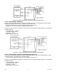
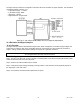
12.2.2 Bi-polar Voltage Amplifiers
Use the following wiring diagram when connecting an amplified transducer, in0line amplifier or DC-DC LVDT with a
bi-polar voltage amplifier to a High-Level Input channel. Examples of such devices include:
• transducers with Option 2a or Option 2b internal amplifiers (with shunt cal)
• Models UBP or UBP-10 Universal In0Line amplifiers (with shunt cal)
• Models MDL, DLA, MDLC, DW7U and DW7S DC-DC LVDTs (no shunt cal)
See “Low Voltage DC-DC LVDTs” for information on wiring Model DLB, DLE and DLF low-voltage DC-DC LVDTs.
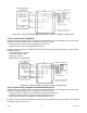
The High-Level Input channel’s Configuration Jumpers must be set as follows for proper operation. See “Excitation
and Signal Jumpers”.
• (+)Excitation supply: “+15 VDC”
• (-)Excitation supply: “-15 VDC”
• Signal type: “voltage”
• Signal reference: “single ended”