
Manual


CF 66 37 Rev. C 2/05
11.2 Wiring
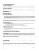
Connect your transducer to an AC/AC-LVDT Input channel by wiring it to the 12-pin connector of that channel. The
System Calibration Sheet that shipped with the instrument describes which cards are installed in each channel.
The pin-out for this connector is shown on the following table.
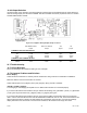
Table 11-1: AC/AC-LVDT Input Channel Pin Connections
Pin Label Function Reference Pin
1 (top) +EXC (+) Excitation 10
2 N/C No connection
3 N/C No connection
4 -EXC (-) Excitation 10
5 +SIG (+) Signal 10
6 -SIG (-) Signal 10
7 +OUT Analog Output 8
8 -OUT Analog Return -
9 N/C No connection
10 DGND Digital Ground -
11 AUX1
Auxiliary Function 1
(connect to pin 10 to activate)
10
12 (bottom) AUX2
Auxiliary Function 2
(connect to pin 10 to activate)
10
The Analog Output and Analog Return pins are electrically isolated from all other pins on the instrument.
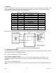
Figure 11-1: Connection of Four- or Five-wire AC/AC-LVDT
11.3 Calibration Procedure
If you are not familiar with operating the instrument in the SETUP menu mode, see “SETUP Menu Mode”. A listing
of all menu items is given in “Setup Menu Reference”.
Step 1: Wire the transducer to the channel’s connector.
Step 2: Enter the CALIBRATION TYPE.
You must have the capability to apply either two, three, or five known displacements to the transducer. The
CALIBRATION TYPE menu item allows you to specify how many known displacements will be applied during
calibration.
Step 3: Enter the CALIBRATION DATA.
Consult the Certificate of Calibration for the transducer when entering information in the CALIBRATION DATA sub-
menu.