
Manual


CF 66 14 Rev. C 2/05
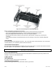
4.5.7 Internal Arrangement
User installable printed circuit boards will slide out of the rear of the case once the case and rear panel have been
removed as described above.
4.5.8 Cleaning
Turn off the instrument and unplug all connectors. Use a soft cloth or tissue and a mild cleaner. Do not use liquid
or aerosol cleaners. Do not allow any cleaner inside the instrument.
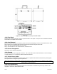
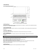
4.5.9 Fuse Replacement
The power-line fuses of AC-powered instruments are located within the instrument’s power entry module on the
rear panel. Use two 2A, 250V fast-blow fuses.
5.0 SYSTEM CONNECTOR
5.1 Introduction
The 25-pin D-subminiature System connector is used for the following:
• Communication by RS-232 or RS-485. RS-232 DCE standard designations have been maintained
• Digital Function Inputs, such as for resetting tare, peak and latched limits
• Open-collector digital Limit Outputs for limits 1 through 4 (not available on DFI 1550)
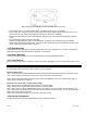
5.2 System Connector Pinout
Table 5-1: System Connector
Pin Name Function Input/Output Reference Pin
1 N/C No Connection N/A
2 RS-232 IN RS-232 Data In Input 7
3 RS-232 OUT RS-232 Data Out Output 7
4 CTS RS-232 Clear to Send (connected to pin 5) N/A N/A
5 RTS RS-232 Request to Send (connected to pin 4) N/A N/A
6 DSR RS-232 Data Set Ready Output 7
7 GND RS-232/RS-485 reference Reference -
8 DCD RS-232 Data Carrier Detect (not connected) N/A N/A
9 FUNC 2 Function Input #2: Clear Peak/Valley & Limits Input 19
10 FUNC 1 Function Input #1: Tare Off for all channels Input 19
11 FUNC 0 Function Input #0 Input 19
12 RS-485 TB RS-485 Transmit B Output 7
13 RS-485 TA RS-485 Transmit A Output 7
14 L1 Limit 1 Output (Open Collector) Output 19
15 L2 Limit 2 Output (Open Collector) Output 19
16 L3 Limit 3 Output (Open Collector) Output 19
17 L4 Limit 4 Output (Open Collector) Output 19
18 N/C No Connection N/A
19 DGND DGND (Digital Ground) Reference
20 DTR RS-232 Data Terminal Ready (not connected) N/A N/C
21 FUNC3 Function Input #3: Tare On for all channels Input 19
22 RI RS-232 Ring Indicator (pulled up to 5V) Output
23 N/C No Connection N/A N/C
24 RS-485 RB RS-485 Receive B Input 7
25 RS-485 RA RS-485 Receive A Input 7
The Limit Output pins and Function Input pins are electrically isolated from the rest of the instrument.
The RS-232 and RS-485 communications pins are electrically isolated from the rest of the instrument.
The RS-232 and RS-485 interfaces are exclusive; an instrument cannot have both.