DCM 465 VOLTAGE BRIDGE AMPLIFIER USER’S GUIDE www.cooperinstruments.
Features • Rugged, Compact and Fully Encapsulated • Complete System - Just Add AC Power • Ready to Use with Screwdriver Wiring • Stable and Accurate Applications • Weighing with Load Cells • Long Term Structural Monitoring • Process Control Pressure Transducers • Low Frequency Strain Measurements Description The DCM 465 is a self-contained, AC powered, signal conditioning module for bridge type instrumentation.
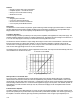
maximum of 1,000 by means of an external resistor connected across terminals 12 and 13. The size of the external resistor can be calculated using the gain formula in the specifications. When doing this, the coarse gain potentiometer should be turned fully clockwise. The fine gain pot can then be used for final gain adjustment. The output offset adjustment range is ±0.5V. The amplifier can withstand input voltages up to 15 Volts without damage.
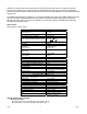
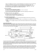
Note: If the ± SENSE are not used in your load cell application, the connections in step C & D need to be followed. If the ±SENSE are going to be used, do not jumper them as described in steps C & D. C. Connect B +, pin 4, to the +excitation of your load cell and jumper the + SENSE, pin 3, to B+, pin 4. D. Connect B-, pin 2, to the -excitation of your load cell and jumper the - SENSE, pin 1, to B-, pin 2. E. Connect the VAC power supply to the AC input lines, pins 6 and 7. II. Turn On Procedure A.
bridge rather than at the output of the supply thereby eliminating this potential source of error. The decision of whether to use the sense leads or not depends entirely on the lead length, its resistance and the effect of that error on the measurement. Application Suggestions The DCM 465 is designed to eliminate many of the ordinary problems associated with bridge type measurements.
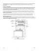
Screw Terminal 1 2 3 4 5 6 7 Terminal Strip Assignments Screw Function Function Terminal -SENSE 8 OUTPUT B9 AMPLIFIER CMN +SENSE 10 +INPUT B+ 11 -INPUT NOT USED 12 EXT. GAIN AC 13 EXT.