
User's Manual


5
DMAN-xxxx-xx
www.omnexcontrols.com
call toll free: 1-800-663-8806
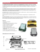
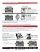
Use the Wiring Diagram and the Connector Diagram below to connect the Expansion module pins directly to the ap-
propriate contacts of the machine electronics. D180 Output Cables are provided with every system to simplify the wir-
ing process. The Wire Color column below only applies to the OMNEX Output Cable configuration. Tips on mounting,
power connections and filtering are also provided under Installation Considerations.
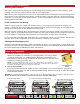
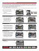
Installing the Expansion Module
Special Functions
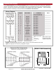
Wiring Diagram
Power Input
(+9V to 30VDC)
Ground
Notes
________________
________________
________________
________________
________________
________________
________________
________________
________________
________________
________________
________________
________________
________________
________________
________________
________________
________________
________________
________________
________________
Functions
Factory Configurable Only
Factory Configurable Only
Unused Output
Unused Output
Unused Output
Unused Output
Unused Output
Unused Output
Unused Output
Digger Dig
Digger Rev
Lift Up
Lift Down
3rd Ext Out
3rd Ext In
2nd Ext Out
2nd Ext In
Rotate CW
Rotate CCW
Winch Up
Winch Down
Wire Colors
Black/Red
White/Black
Blue/White
Blue/Black
Black/White
Green/Black
Red/White
Orange
White
Green/Black/White
Green
Red/Black/White
White/Red/Black
Orange/Red
Orange/Black
Blue/Red
White/Red
Red/Green
Orange/Green
Black/White/Red
Red
Black
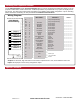
Module 1
Module 2
Module 3
Module 4
Module 5
Module 6
Module 7
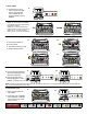
Outputs: 14 solid state, high-side driver Current Control outputs 5A max. each, total combined current 15A
Inputs: All output pins can be factory configured as inputs.
D180 Module
Internal Wiring
Pin-Output
B7
B8
B12 - 19
B11 - 18
B10 - 17
A1 - 16
A2 - 15
A4 - 14
B9 - 13
B6 - 12
B5 - 11
B4 - 10
B3 - 9
B2 - 8
B1 - 7
A12 - 6
A10 - 5
A11 - 4
A9 - 3
A8 - 2
A7 - 1
A5
A6
A3