
User's Manual


6
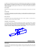
POWER:
Indicates that 12 volt DC power is applied to the receiver.
ID:
Indicates that information from the transmitter is being successfully received. If the light flickers
occasionally this indicates that interference is present on some frequencies. This is not a problem
since this is a spread spectrum system and changes frequency many times each second.
LINK:
Indicates that the radio link between the transmitter and receiver is reliable. If the link is not
reliable, power is removed from the receiver output drivers.
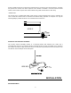
CONFIGURING THE PROPORTIONAL SPEED OUTPUT:
The receiver contains a configuration panel that allows you to customize the operation of the function
speed control. The panel appears as shown below:
To enable the configuration panel, plug in the user configuration key supplied. The display will initially be
displaying "Output" 1 + , no "Param" lights will be illuminated, and the "Value" lights will be displaying the
Start PWM and MAX PWM as solid lights, and the actual speed output as a flashing light. The flashing
light will move as the speed dial on the transmitter is rotated. You will also see the green light next to the
1+ output go brighter and dimmer.
OPERATION
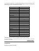
Note: You will notice that the control panel has 6 "output" lights. This is because the receiver is capable of
controlling the parameters for up to 6 proportional functions. In this particular application, however, only a
single proportional output is needed, and this has been assigned to output #1. Also, the Parameter setting
options: Threshold, Ramp Up and Ramp Down, will not apply to the simple potentiometer control provided
on the Altec system. (These are used in other applications that require joystick type controls). In