
Installation Manual


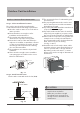


Pipe
Reamer
Point dow
n
Fig. 7.5
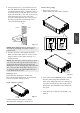
CAUTION
DO NOT deform pipe while cutting. Be extra
careful not to damage, dent, or deform the pipe
while cutting. This will drastically reduce the
heating efficiency of the unit.
1. Make sure that the pipe is cut at a perfect
90° angle. Refer to Fig. 7.4 for examples
of bad cuts
Oblique
Rough
Warped
90°
Fig. 7.4
Step2: Remove burrs.
Burrs can aect the air-tight seal of refrigerant
piping connection. They must be completely
removed.
1. Hold the pipe at a downward angle to
prevent burrs from falling into the pipe.
2. Using a reamer or deburring tool, remove
all burrs from the cut section of the pipe.
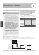
Refrigerant Piping
Connection
Size of joint pipes for indoor unit
Size of joint pipes for 410A indoor unit
Table 7.3
Size of joint pipes for outdoor unit
Base on the following tables, select the diameters
of the outdoor unit connective pipes. In case of the
main accessory pipe larger than the main pipe, take
the larger one for the selection.
Step1: Cut pipes
When preparing refrigerant pipes, take extra
care to cut and flare them properly. This will
ensure efficient operation and minimize the
need for future maintenance.
1. Measure the distance between the indoor
and outdoor units.
2. Using a pipe cutter, cut the pipe a little
longer than the measured distance.
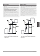
Refrigerant Piping Connection Instructions
CAUTION
• The branching pipe must be installed
horizontally. An angle of more than 10° may
cause malfunction.
• DO NOTinstall the connecting pipe until both
indoor and outdoor units have been installed.
• Insulate both the gas and liquid piping to
prevent water leakage.
Page 20
Table 7.2
Permitted length
Piping
length
Total piping length 18K+18K 98’/30m L+Max
(L1, L2)
24K+24K
30K+30K
164’/50m
(farthest distance from
the line pipe branch)
49’/15m L1, L2
(farthest distance from
the line pipe branch)
32.8’/10m L1-L2
Drop
height
Drop height between
indoor and outdoor unit
65.6’/20m H1
Drop height between
two indoor units
1.6’/0.5m H2
Gas side
Capacity
of indoor
unit (A)
Size of main pipe(mm)
Liquid side
Ø0.5”(12.7)
Ø0.626”(15.9)
Ø0.626”(15.9)
Ø0.25”(6.35)
Ø0.375”(9.5)
Ø0.375”(9.5)
18K
24K
30K
CE-FQZHN-01C
CE-FQZHN-01C
Available
branching pipe
CE-FQZHN-01C
Model
Gas side Liquid side
Ø0.626”(15.9)
Ø0.626”(15.9)
Ø0.626”(15.9)
Ø0.375”(9.5)
Ø0.375”(9.5)
Ø0.375”(9.5)
the size of main pipe(mm)
36K
48K
60K
Size of joint pipes for 410A outdoor unit
Table 7.4
The 1st
branching pipe
CE-FQZHN-01C
CE-FQZHN-01C
CE-FQZHN-01C