
Cut Sheet

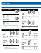


7
“D” dimension indicates maximum panel thickness hub will accommodate.
CONDUIT OR PIPE SIZE
Dimensions
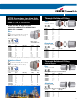
Spacing Chart
Size A B C D
E
FG HMin. Max. Min. Max.
3
/8 1
3
/2 1
1
/8
21
/32
1
/8 .468 .493
3
/8 NPT
3
/8 NPSM 60°
43
/64
11
/16
1
/2 1
11
/32 1
7
/16
13
/16
3
/16 .591 .622
1
/2 NPT
1
/2 NPSM 60°
55
/64
7
/8
3
/4 1
15
/32 1
23
/32
29
/32
3
/16 .783 .824
3
/4 NPT
3
/4 NPSM 60° 1
1
/16 1
1
/8
11
21
/32 21
1
/32
1
/4 .997 1.049 1 NPT 1 NPSM 60° 1
21
/64 1
3
/8
1
1
/4 1
11
/16 2
3
/8 1
1
/32
1
/4 1.311 1.380 1
1
/4 NPT 1
1
/4 NPSM 60° 1
43
/64 1
3
/4
1
1
/2 1
11
/16 2
3
/4 1
1
/32
1
/4 1.529 1.610 1
1
/2 NPT 1
1
/2 NPSM 60° 1
59
/64 2
21
3
/4 3
1
/4 1
3
/32
1
/4 1.964 2.067 2 NPT 2 NPSM 60° 2
25
/64 2
1
/2
2
1
/2 2
7
/32 3
3
/4 1
9
/32
1
/4 2.346 2.469 2
1
/2 NPT 2
1
/2 NPSM 60° 2
57
/64 3
32
5
/16 4
3
/8 1
3
/8
1
/4 2.915 3.068 3 NPT 3 NPSM 45° 3
33
/64 3
5
/8
3
1
/2 2
3
/8 51
7
/16
1
/4 3.371 3.548 3
1
/2 NPT 3
1
/2 NPSM 45° 4
1
/64 4
1
/8
42
7
/16 5
1
/2 1
1
/2
1
/4 3.825 4.026 4 NPT 4 NPSM 45° 4
33
/64 4
5
/8
52
15
/16 6
7
/8 2
1
/4 4.795 5.047 5 NPT 5 NPSM 45° 5
37
/64 5
11
/16
63 7
11
/16 2
5
/16 5.762 6.065 6 NPT 6 NPSM 45° 6
41
/64 6
3
/4
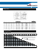
K
(Mounting Hole)
Conduit
Size
1/4 3/8 1/2 3/4 1 1-1/4 1-1/2 2 2-1/2 3 3-1/2 4 5 6
3/8 1-5/32 1-1/4
1/2 1-5/16 1-13/32 1-9/16 .
3/4 1-7/16 1-17/32 1-11/16 1-13/16
1 1-9/32 1-11/16 1-27/32 1-31/32 2-1/8
1-1/4 1-25/32 1-7/8 2-1/32 2-5/32 2-5/16 2-1/2
1-1/2 1-31/32 2-1/16 2-7/32 2-11/32 2-1/2 2-11/16 2-7/8
2 2-7/32 2-5/16 2-15/32 2-19/32 2-3/4 2-15/16 3-1/8 3-3/8
2-1/2 2-15/32 2-9/16 2-23/32 2-27/32 3 3-3/16 3-3/8 3-5/8 3-7/8
3 2-25/32 2-7/8 3-1/32 3-5/32 3-5/16 3-1/2 3-11/16 3-15/16 4-3/16 4-1/2
3-1/2 3-3/32 3-3/16 3-11/32 3-15/32 3-5/8 3-13/16 4 4-1/4 4-1/2 4-13/16 5-1/8
4 3-11/32 3-7/16 3-19/32 3-23/32 3-7/8 4-1/16 4-1/4 4-1/2 4-3/4 5-1/16 5-3/8 5-3/4
5 4-1/32 4-1/8 4-9/32 4-13/32 4-9/16 4-3/4 4-15/16 5-3/16 5-7/16 5-3/4 6-1/16 6-3/16 7-1/8
6 4-13/32 4-1/2 4-21/32 4-25/32 4-15/16 5-1/8 5-5/16 5-9/16 5-13/16 6-1/8 6-7/16 6-11/16 7-3/8 7-3/4
19/32 11/16 27/32 31/32 1-1/8 1-5/16 1-1/2 1-3/4 2 2-5/16 2-5/8 2-7/8 3-9/16 3-15/16
Minimum space from center of pipe or conduit to nearest obstruction.
1. Dimensions in top row (boxed squares) are centers for conduits of same size.
Example: How close may 3” conduits be spaced? Answer 4
1
/2”
2. Dimensions in light blue shaded squares are for centers of conduits
NOT of the same size. Example: What is the minimum spacing for 2”
and
3
/4” conduit? Read down column marked 2” to figure opposite
3
/4”
and find dimensions is 2
19
/32”.
Note. Minimum spacing dimensions as shown will give
approximately
1
/8” clearance between locking nuts.