
Installation Manual

Make sure all connections are tight, secure and safe.
11.0 CHECK YOUR WORK
These steps need to be completed with your personal safety in mind. Before
installing fuses, complete these simple time-saving checks:
11.1. MEASURE VOLTAGE (VOC)
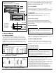
Check the open circuit positive voltage (Voc) from each individual solar array string
to the negative bus bar. Ensure each Voc is the proper polarity and within the
intended range. Voc does not vary much with irradiance and temperature conditions.
11.2. CHECK GROUND CURRENTS
Check the DC current from each individual string (fuse holder) to ground. If current is
present, locate and repair any ground faults.
11.3. INSERT FUSES
Check that the fuses are the proper rating and type and insert fuses into fuse
holders and secure it in the closed position.
11.4. FINAL INSPECTION
Check the DC voltage from the combined output lug to the negative bar. Ensure
voltage is the proper polarity and within the desired voltage range.
Check to ensure that all conduit connections are clean and tight and are properly
sealed against environmental concerns.
Close and secure the enclosure door.
12.0 MAINTENANCE
Please review this manual fully before beginning work on combiner boxes. Follow
all safety guidelines and warnings.
Every 6 months inspect and re-torque the wire connections.
We recommend an Electrical Preventive Maintenance Program as described
in the National Fire Protection Association Bulletin NFPA 70B:
Recommended Practice for Electrical Equipment Maintenance
(www.nfpa.org).
WARNING
To prevent injury, death, or damage to your photovoltaic system, extreme caution should
be taken whenever entering the control cabinet due to energized components.
Photovoltaic panels generate power whenever exposed to ANY light. Cover the panel
entirely prior to wiring or servicing with an opaque cover.
Prior to installation or servicing, switch all disconnects to OFF position and use only
insulated tools and proper P.P.E.
WARNING
To prevent component damage or electric shock, avoid touching any component or any
part of the circuitry while the equipment is operating. Do not place heavy loads on
associated system cables or maneuver them in a manner which may expose personnel
or equipment to current. Do not connect system cables when the terminals are wet or
damp. Do not disconnect cables under load.
IF 1598 • 12/10 Copyright © 2010, Cooper Industries, Inc. Page 3
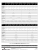
Number of input circuits 1 through 4 5 through 6 7 through 12 13 through 20 21 through 24
Positive Input Terminal Torque (in-lbs) 16-22 16-22 16-22 16-22 16-22
Negative Input Terminal Torque (in-lbs) 20 35 35 35 35
Positive Output Terminal Torque (in-lbs) 35 35 120 275 120
Negative Output Terminal Torque (in-lbs) 120 500 120 275 120
Ground Output Terminal Torque (in-lbs) 20-35 20-35 275 275 275
Table 1