
Electronics Network Card User Manual

56
www.cooperbussmann.com/BussmannWirelessResources
Cooper Bussmann Wireless Ethernet & Device Server BU-945U-E 802.11 DSSS User Manual
3A1582Rev1.6
Access Point Configuration
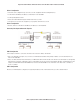
• Connect straight through Ethernet cable between PC and BU-945U-E
• Ensure configuration PC and BU-945U-E are setup to communicate on the same network
• Set DIP switch to SETUP
• Power up unit, and wait for LINK led to cease flashing
• Adjust PC network settings
• Set Configuration PC network card with network setting of IP address 192.168.0.1, netmask 255.255.255.0
• Open configuration webpage with Internet Explorer at address 192.168.0.1XX/
• When prompted for password, enter default username “user” and password “user”
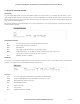
• Enter “Network,” and select Operating Mode as Access Point
• Device Mode should be set to Router
• Set the Gateway IP address to 192.168.0.1
• Set the Ethernet IP address to 192.168.0.200, network mask 255.255.255.0
• Set the Wireless IP address to 169.254.102.54, network mask 255.255.255.0
• Select the Radio Encryption required, and enter encryption keys or passphrase if necessary
• Set DIP switch to RUN
• Click on button Save to Flash and Reset. Webpage will display that message indicating details are being written to flash. Wait for
BU-945U-E to reboot before removing power. Enter a System Generator String.
Client Configuration
Perform the same configuration steps as the Access Point configuration with the following differences:
• Enter “Network,” and select Operating Mode as Client
• Device Mode should be set to Bridge
• Set the Gateway IP address to 169.254.102.54
• Set the Ethernet IP address to 169.254.102.53, network mask 255.255.255.0
• Set the Wireless IP address to 169.254.102.53, network mask 255.255.255.0
• Click on button Save to Flash and Reset. Webpage will display that message indicating details are being written to flash. Wait for
BU-945U-E to reboot before removing power.
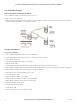
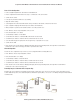
Extending Range of a Network with a Repeater Hop
Configure units as described in the “Extending a wired network” example above. Place the Access Point at the remote intermediate repeater
location. Additional repeaters can be added using Wireless Distribution System (WDS) – refer section 3.11 ”Multiple AP Repeater Mesh Network”
for further details.