
Electronics Network Card User Manual

www.cooperbussmann.com/BussmannWirelessResources
Cooper Bussmann Wireless Ethernet & Device Server BU-945U-E 802.11 DSSS User Manual
553A1582Rev1.6
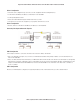
Client 1 Configuration
• Perform the same configuration steps as the Access Point configuration with the following differences:
• Set the Ethernet and Wireless IP addresses of BU-945U-E to 192.168.0.201
• Set the Operating Mode to Client.
• Ensure the ESSID and Radio Encryption method match the Access Point.
• If encryption is used, ensure the encryption keys or passphrase match the Access Point.
Client 2 Configuration
• As above, however set the Ethernet and Wireless IP addresses as 192.168.0.202
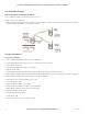
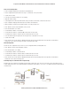
Connecting Two Separate Networks Together
LAN A Configuration
In this example, network A is connected to the internet via a router at IP address 192.168.0.1.
• Devices on LAN A that only require access to devices on LAN A and B, should have their gateway IP address set to the BU-945U-E Access
Point as 192.168.0.200.
• Devices on LAN A, that must interact with devices on LAN A and B and the internet should set the internet router 192.168.0.1 as their gateway,
and must have a routing rule established for devices on Network B. On PCs, this may be achieved with the MS-DOS command ROUTE. For this
example use: ROUTE ADD 169.254.102.0 MASK 255.255.255.0 192.168.0.200. For more information on the DOS “Route” command see
section 4.3 “Utilities”
LAN B Configuration
All devices on LAN B should be configured so their gateway IP address is that of the BU-945U-E Access Point as 169.254.102.54