
Electronics Network Card User Manual

54
www.cooperbussmann.com/BussmannWirelessResources
Cooper Bussmann Wireless Ethernet & Device Server BU-945U-E 802.11 DSSS User Manual
3A1582Rev1.6
3.21 Configuration Examples
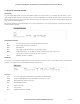
Setting a BU-945U-E to Factory Default Settings
Access configuration webpage on the BU-945U-E. Refer section”3.3.”
• Click on “System Tools” Menu Item
• Click on Factory Default Configuration Reset, and wait for unit to reset. While the module executes the reset sequence the OK LED will flash.
The OK LED will turn green when the reset sequence is complete.
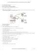
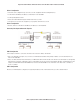
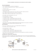
Extending a Wired Network
Access Point Configuration
• Connect straight through Ethernet cable between PC and BU-945U-E.
• Ensure configuration PC and BU-945U-E are setup to communicate on the same network
• Set DIP switch to SETUP mode.
• Power up unit, and wait for the OK LED to cease flashing.
• Adjust PC network settings
• Set Configuration PC network card with network setting of IP address 192.168.0.1, netmask 255.255.255.0
• Open configuration webpage with Internet Explorer at address 192.168.0.1XX/ where XX is the last two digits of the module’s serial number
• When prompted for password, enter default username “user” and password “user”
• Click “Network”, and select Operating Mode as Access Point.
• Select Device Mode as Bridge.
• Change the Gateway IP Address to 192.168.0.1
• Change the Ethernet and Wireless IP addresses to 192.168.0.200
• Change Ethernet and Wireless Subnet masks to 255.255.255.0
• Enter a System Address (ESSID) string
• Select the Radio Encryption required.
• Set DIP switch to RUN
• Save the changes and unit will restart with new settings.