
Electronics Network Card User Manual
www.cooperbussmann.com/BussmannWirelessResources
Cooper Bussmann Wireless Ethernet & Device Server BU-945U-E 802.11 DSSS User Manual
253A1582Rev1.6
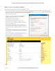
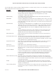
Network Settings Webpage Fields
Operating Mode Used to select Access Point (Infrastructure), Client (Infrastructure). By default this is set to Client.
Device Mode Used to select Bridge or Router mode. By default this is set to Bridge.
Bridge STP Checking this box enables Spanning Tree protocol in bridged networks. See to section
3.10 “Spanning Tree Algorithm / Redundancy” for more details
Bridge Priority This is the priority associated with the Spanning tree protocol. Use lower numbers to move this station
towards the root of the Spanning Tree, and use higher number here to move the station towards the
leaves of the tree.
Default Gateway This is the address that the device will use to forward messages to remote hosts that are not connected
to any of the local bridged network (Ethernet or Wireless). This is only required if the wired LAN has a
Gateway unit which connects to devices beyond the LAN - for example, Internet access. If there is no
Gateway on the LAN, set to the same address as the Access Point - that is, the “Ethernet IP Address”
below. Refer to section 3.13 “ Routing Rules” for more information.
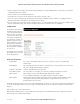
Obtain IP Address Automatically Checking this item enables DHCP client on the BU-945U-E. A DHCP client requests its IP address from
a DHCP server which assigns the IP Address automatically. For more information, refer to section 3.8
“DHCP Server Configuration”, Default is unchecked.
MAC Address This is the unique hardware address of the BU-945U-E and is assigned in the Factory. The BU-945U-E
has two MAC addresses, one for each interface (Ethernet and Wireless) The Ethernet MAC is the
primary MAC Address.
IP Address The IP address of the BU-945U-E on its wired (Ethernet Interface) port and wireless (Wireless Interface)
port. This should be set to the IP address you require. If the device mode is set to bridge, then the wired
and wireless ports will have the same IP address.
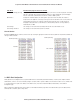
IP Subnet Mask The IP network mask of the BU-945U-E on its wired (Ethernet Interface) port and wireless (Wireless
Interface) port. This should be set to appropriate subnet mask for your system (Typically 255.255.255.0).
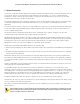
System Address (ESSID) A BU-945U-E wireless network comprises modules with the same "system address.” Only modules with
the same system address will communicate with each other. The system address is a text string 1 to 31
characters in length. Select a text string which identifies your system.
Desired BSSID To force a client/station to always connect to the same Access Point enter the MAC address of that
Access Point in the Desired BSSID field (Note that the ESSID of the Access Point must also match the
configured ESSID of the client).
Radio Encryption Select the desired radio Encryption level, press “Save Changes” button and then select “Configure on
Security Page” link. Encryption key, passphrase, etc. is entered on the “Security Menu”
(See section below for details)
Save Changes Save changes to non-volatile memory. The module will need to be restarted before the changes
take effect.
Save Changes and Reset Save settings to non-volatile memory, and reboot BU-945U-E. Once the module has completed the
reboot sequence, all changes are in effect.