
Electronics Network Card User Manual


www.cooperbussmann.com/BussmannWirelessResources
Cooper Bussmann Wireless Ethernet & Device Server BU-945U-E 802.11 DSSS User Manual
173A1582Rev1.6
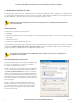
LED Indication
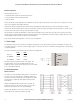
The following table details the status of the indicating LEDs on the front panel under normal operating conditions.
LED Indicator Condition
Meaning
OK GREEN Normal Operation
OK Flashing RED/GREEN Module Boot Sequence
Radio RX GREEN flash Radio receiving data (Good Signal Strength)
Radio RX RED flash Radio receiving data (Low Signal strength)
TX/LINK GREEN Radio Connection Established
TX/LINK RED Flash Radio Transmitting
RS-232 GREEN flash Data sent from RS-232 Serial Port
RS-232 RED flash Data received to RS-232 Serial Port
LAN ON Link Established on Ethernet port
LAN Flash Activity on Ethernet port.
RS-485 GREEN flash Data sent from RS-485 Serial Port
RS-485 RED flash Data received to RS-485 Serial Port
DIO GREEN Digital Input is grounded.
DIO RED Digital Output is active
DIO Off Digital Output OFF and Input is open circuit.
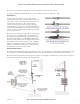
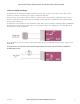
The Ethernet RJ45 port incorporates two indication LEDs. The LINK LED comes on when there is a connection on the Ethernet port, and will blink
off briefly when activity is detected on the Ethernet Port. The 100MB LED indicates that the connection is at 100 MBit/Sec. The 100MB LED will
be off for 10MB/Sec connection.
Other conditions indicating a fault are described in Chapter Four - DIAGNOSTICS.
3.2 Selecting a Channel
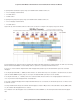
802.11 (900 MHz) Channels
The BU-945U-E conforms to the IEEE 802.11 Wireless LAN specification and supports various channels depending on regulations within the
country of use.
If operating in the US, Canada, the frequency range is 902 to 928MHz and the available channels are:
• 9 x non overlapping 1.25MHz channels
• 9 x partially overlapping 2.5MHz channels
• 4 x non overlapping 5MHz channels
• 4 x overlapping 10MHz channels
• 2 x overlapping 20MHz channels.
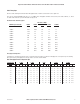
If operating in Australia the frequency range is 915-928MHz and the available channels are:
• 4 x non overlapping 1.25MHz channels
• 4 x partially overlapping 2.5MHz channels
• 3 x overlapping 5MHz channels
• 1 x 10MHz channel