Read and Retain for Future Reference Cooper Bussmann BU-945U-E 802.11 DSSS Wireless Ethernet & Device Server User Manual Version 1.6 3A1582Rev1.
Cooper Bussmann Wireless Ethernet & Device Server BU-945U-E 802.11 DSSS User Manual Cooper Bussmann Application Engineering • Phone 8:00 a.m - 5:00 p.m. Central, M-F (636) 527-1270 • Fax: (636) 527-1607 • E-mail: FuseTech@cooperindustries.com Thank you for your selection of the BU-945U-E Wireless Ethernet Modem. We trust it will give you many years of valuable service. ATTENTION! Incorrect termination of supply wires may cause internal damage and will void warranty.
Cooper Bussmann Wireless Ethernet & Device Server BU-945U-E 802.11 DSSS User Manual Important Notice Cooper Bussmann products are designed to be used in industrial environments, by experienced industrial engineering personnel with adequate knowledge of safety design considerations. Cooper Bussmann radio products are used on unprotected license-free radio bands with radio noise and interference.
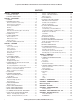
Cooper Bussmann Wireless Ethernet & Device Server BU-945U-E 802.11 DSSS User Manual CONTENTS CHAPTER 1 - INTRODUCTION . . . . . . . . . . . . . . . . . . . . . . . . . .5 1.1 NETWORK TOPOLOGY . . . . . . . . . . . . . . . . . . . . . . . . . . . .5 1.2 GETTING STARTED QUICKLY . . . . . . . . . . . . . . . . . . . . . . .8 CHAPTER 2 - INSTALLATION . . . . . . . . . . . . . . . . . . . . . . . . . . .9 2.1 GENERAL . . . . . . . . . . . . . . . . . . . . . . . . . . . . . . . . . . . . .9 2.
Cooper Bussmann Wireless Ethernet & Device Server BU-945U-E 802.11 DSSS User Manual CHAPTER 1 - INTRODUCTION The BU-945U-E Industrial 802.11 Wireless Ethernet module provide wireless connections between Ethernet devices and/or Ethernet wired networks (LAN’s) and complies with relevant IEEE 802.11 standard. BU-945U-E 802.11 630mW max power The BU-945U-E uses a 900 MHz Direct Sequence Spread Spectrum (DSSS) wireless transceiver.
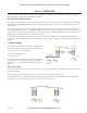
Cooper Bussmann Wireless Ethernet & Device Server BU-945U-E 802.11 DSSS User Manual The second diagram shows an existing LAN being extended using BU-945U-Es. In this example, the Access Point is configured at the LAN end although the wireless link will still work if the Client is at the LAN end. An Access Point can connect to multiple Clients. In this case, the Access Point should be the “central” unit.
Cooper Bussmann Wireless Ethernet & Device Server BU-945U-E 802.11 DSSS User Manual Bridge vs. Router Each BU-945U-E is configured with an IP address for the Ethernet side, and another for the wireless side. A Bridge connects devices within the same Ethernet network - for example, extending an existing Ethernet LAN. For a Bridge, the IP address for the wireless side is the same as the Ethernet side. A Router connects devices on different LANs.
Cooper Bussmann Wireless Ethernet & Device Server BU-945U-E 802.11 DSSS User Manual 1.2 Getting Started Quickly Most applications for the BU-945U-E require little configuration. The BU-945U-E has many sophisticated features, however if you don’t require these features, this section will allow you to configure the units quickly. First, read Chapter 2, “Installation.” The BU-945U-E requires an antenna and a power supply.
Cooper Bussmann Wireless Ethernet & Device Server BU-945U-E 802.11 DSSS User Manual CHAPTER 2 - INSTALLATION 2.1 General The BU-945U-E modules are housed in a rugged aluminum case, suitable for DIN-rail mounting. Terminals will accept wires up to 2.5 mm2 (12 gauge) in size. All connections to the module must be SELV (Safety Extra Low Voltage). Normal 110-250V mains supply must not be connected to any terminal of the BU-945U-E module. Refer to Section 2.3 Power Supply.
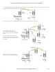
Cooper Bussmann Wireless Ethernet & Device Server BU-945U-E 802.11 DSSS User Manual Bench test and Demo System Setup Care must be taken with placement of antenna in relation to the radios and the other antennas. Strong radio signals can saturate the receiver, hindering the overall radio communications. When setting up a Bench test/Demo or a short range system the following considerations should be taken into account for optimum radio performance and reduced signal saturation.
Cooper Bussmann Wireless Ethernet & Device Server BU-945U-E 802.11 DSSS User Manual The net gain of the antenna/cable configuration is determined by adding the antenna gain and the cable loss. For example, an 8dBi antenna (5.8dBd) with 10 meters of Cellfoil (3dBd) has a net gain of 2.8dB (5.8dB – 3dB). Installation tips Connections between the antenna and coaxial cable should be carefully taped to prevent ingress of moisture.
Cooper Bussmann Wireless Ethernet & Device Server BU-945U-E 802.11 DSSS User Manual Directional Antennas Directional antennas can be a: • Yagi antenna with a main beam and orthogonal elements • Directional radome, which is cylindrical in shape • Parabolic antenna A directional antenna provides high gain in the forward direction, but lower gain in other directions. This may be used to compensate for coaxial cable loss for installations with marginal radio path.
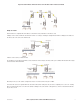
Cooper Bussmann Wireless Ethernet & Device Server BU-945U-E 802.11 DSSS User Manual DB9 Connector Pinouts Pin Name Direction Function 1 DCD Out Data carrier detect 2 RD Out Transmit Data – Serial Data Output (from DCE to DTE) 3 TD In Receive Data – Serial Data Input (from DTE to DCE) 4 DTR In Data Terminal Ready 5 SG -- Signal Ground 6 DSR Out Data Set Ready - always high when unit is powered on.
Cooper Bussmann Wireless Ethernet & Device Server BU-945U-E 802.11 DSSS User Manual Shorter runs of 485 cables may not require the termination resistors to be enabled. 14 www.cooperbussmann.com/BussmannWirelessResources 3A1582Rev1.
Cooper Bussmann Wireless Ethernet & Device Server BU-945U-E 802.11 DSSS User Manual 2.5 Discrete (Digital) Input/Output The BU-945U-E has one on-board discrete/digital I/O channel. This channel can act as either a discrete input or discrete output. It can be monitored, or set remotely, or alternatively used to output a communications alarm status.
Cooper Bussmann Wireless Ethernet & Device Server BU-945U-E 802.11 DSSS User Manual CHAPTER 3 - OPERATION 3.1 Start-up “Access Point” Start-up When an Access Point (AP) unit starts up it will immediately begin transmitting periodic messages, called beacons on the configured channel. Beacons include information that a Client may examine in order to identify if the Access Point is suitable for link establishment.
Cooper Bussmann Wireless Ethernet & Device Server BU-945U-E 802.11 DSSS User Manual LED Indication The following table details the status of the indicating LEDs on the front panel under normal operating conditions.
Cooper Bussmann Wireless Ethernet & Device Server BU-945U-E 802.11 DSSS User Manual If operating in New Zealand the frequency range is 921-928MHz and the available channels are: • 2 x non overlapping 1.25MHz channels • 1 x 2.5MHz channel • 1 x 5MHz channel If operating in Hong Kong the frequency range is 922-925MHz and the available channels are: • 2 x non overlapping 1.25MHz channels • 1 x 2.5MHz channel Regions will only show the available channels for that location.
Cooper Bussmann Wireless Ethernet & Device Server BU-945U-E 802.11 DSSS User Manual Radio Throughput Below is a table showing the maximum TCP/IP throughput based on channel selection and receiver signal level. There are five channel bandwidths (20, 10, 5, 2.5, & 1.25MHz). These throughput estimations are based on perfect radio conditions, i.e.
Cooper Bussmann Wireless Ethernet & Device Server BU-945U-E 802.11 DSSS User Manual 3.3 Configuring the Unit for the First Time The BU-945U-E has a built-in web server, containing web pages for analyzing and modifying the module’s configuration. The configuration can be accessed using Microsoft® Internet Explorer version 7 or greater. This program is shipped with Microsoft Windows or may be obtained freely via the Microsoft® website.
Cooper Bussmann Wireless Ethernet & Device Server BU-945U-E 802.11 DSSS User Manual Method 1 - Set PC to same network as BU-945U-E Connect the Ethernet cable between unit and the PC configuring the module. • Set the Factory Default Switch to the SETUP position. This will always start the BU-945U-E with Ethernet IP address 192.168.0.1XX, subnet mask 255.255.255.0, gateway IP 192.168.0.1 and the radio disabled.
Cooper Bussmann Wireless Ethernet & Device Server BU-945U-E 802.11 DSSS User Manual To resume normal configured operation when Configuration is complete, switch Factory Default dip-switch on the BU-945U-E to RUN and cycle power. Note: Security Certificates. Configuration of the BU-945U-E uses an encrypted link (https). The security certificate used by the BU-945U-E is issued by Cooper Bussmann and matches the IP address 192.168.0.100.
Cooper Bussmann Wireless Ethernet & Device Server BU-945U-E 802.11 DSSS User Manual • Enter the IP address for the BU-945U-E into the Internet Explorer Address bar e.g. http://10.10.0.6 which is the IP address you temporarily configured with the ifconfig command. • Enter the username “user” and default password “user.” • You should now be connected to the main index page on the modem as per figure 1 above.
Cooper Bussmann Wireless Ethernet & Device Server BU-945U-E 802.11 DSSS User Manual 3.5 Network Configuration You can view or modify Ethernet network parameters by selecting the “Network” menu. When prompted for username and password, enter “user” as the username, and “user” as the password in the password field (This is the factory default – See section 3.17 “Module Information Configuration” to change).
Cooper Bussmann Wireless Ethernet & Device Server BU-945U-E 802.11 DSSS User Manual Network Settings Webpage Fields Operating Mode Used to select Access Point (Infrastructure), Client (Infrastructure). By default this is set to Client. Device Mode Used to select Bridge or Router mode. By default this is set to Bridge. Bridge STP Checking this box enables Spanning Tree protocol in bridged networks. See to section 3.
Cooper Bussmann Wireless Ethernet & Device Server BU-945U-E 802.11 DSSS User Manual Security Menu Select the Radio Encryption level from the drop down menu on the Main index page and then press the “Save Changes” button. The default setting is “None.” Available encryption levels are - “None,” “WEP (64-bit),” “WEP (128-bit),” “WPA PSK (TKIP),” “WPA PSK (AES),” “WPA2 PSK (AES),” “WPA PSK/ WPA2 PSK” and WPA-Enterprise.
Cooper Bussmann Wireless Ethernet & Device Server BU-945U-E 802.11 DSSS User Manual For optimal security a passphrase consisting of a combination of letters and numbers (i.e., not just a simple word or phrase) as well as upper and lower case. E.g., “WiReLeSs TeChNoLoGy 2010” WPA Enterprise - Supplicant Configuration Username / Password: User credentials that match a valid user on the RADIUS server. Enable Debug: Must only be used during commissioning and only if requested by Cooper Bussmann Support.
Cooper Bussmann Wireless Ethernet & Device Server BU-945U-E 802.11 DSSS User Manual 3.6 Normal Operation After addresses are configured, the units are ready for operation. Refer to section 1 for an explanation on the operation of a Bridge and Router. Transparent Bridge Operation A bridge connects several Ethernet networks together, and makes them appear as a single Ethernet network to higher protocol layers. By default, the BU-945U-E is configured as a transparent bridge.
Cooper Bussmann Wireless Ethernet & Device Server BU-945U-E 802.11 DSSS User Manual Select the “Radio” Menu to change the following configuration parameters. If a change is made, you need to select “Save Changes” to retain the changes. Changes will not take effect until the unit is reset. Radio Mode BU-945U-E Only Supports the 802.11 Standard Transmit Power This allows adjustment of the radio power.
Cooper Bussmann Wireless Ethernet & Device Server BU-945U-E 802.11 DSSS User Manual Radio Mode BU-945U-E Only Supports the 802.11 Standard Background Scanning (STA only) Enabling this option will allow a modem to periodically rescan for Access Points keeping the connectivity page up to date with current system information. Default is off. Note: Enabling this option will slightly increase overall radio communications. Rescan time is fixed at 300sec (5min).
Cooper Bussmann Wireless Ethernet & Device Server BU-945U-E 802.11 DSSS User Manual 3.9 DHCP Server Configuration The BU-945U-E is able to act as a DHCP server, supplying IP addresses automatically to other DHCP Client devices. Note that the BU-945U-E units need to act in conjunction with their connected devices. If a connected device is a DHCP server, the local and remote BU-945U-E units can be configured as DHCP Clients and receive IP addresses from the server device.
Cooper Bussmann Wireless Ethernet & Device Server BU-945U-E 802.11 DSSS User Manual The Spanning Tree Protocol implemented is IEEE 802.1d compatible. The algorithm forms a loop-free network by blocking traffic between redundant links in the network. These blocked links are placed in a standby condition, and may be automatically enabled to repair the network if another link is lost. The Spanning Tree Algorithm maintains a single path between all nodes in a network, by forming a tree-like structure.
Cooper Bussmann Wireless Ethernet & Device Server BU-945U-E 802.11 DSSS User Manual A WDS bridge interface allows traffic to be bridged to another Access Point on the same IP network. WDS bridge interfaces do not require additional IP Address configuration, as they are bridged with the standard wireless interface that is used for connections to associated clients. All of the WDS interfaces on the one Access Point may be bridged if required.
Cooper Bussmann Wireless Ethernet & Device Server BU-945U-E 802.11 DSSS User Manual Example – Extending range using WDS One of the most common uses for WDS is to extend the range of the wireless network using repeaters. The diagram above illustrates a simple example where the four Access Points are all at fixed locations (each of the Access Points could, of course, have one or more client/stations connected).
Cooper Bussmann Wireless Ethernet & Device Server BU-945U-E 802.11 DSSS User Manual Example - Roaming with WDS Access Points Another common use for WDS is extending the range across a large wireless network but allowing roaming connections between access points or being able to switch to the next Access Point when out of range of the previous Access Point. The diagram above shows a bridging network with a number of Access Points all with the same SSID, network structure, etc.
Cooper Bussmann Wireless Ethernet & Device Server BU-945U-E 802.11 DSSS User Manual The configuration for Site A and B are shown below. In this example, Site B uses its primary access point to act as an access point for Virtual Stations on Site A and D, and uses a Virtual Station to act as a client to Site C. Site A uses two Virtual Stations to act as clients to Site B and to Site C.
Cooper Bussmann Wireless Ethernet & Device Server BU-945U-E 802.11 DSSS User Manual Example – WDS Routed Network An example of using WDS router interfaces to achieve a similar physical topology to the WDS bridge example discussed earlier is illustrated below. In both examples, there are four WDS Access points each with the possibility of having their own client/stations associated. In both examples A, B, C, and D can all exchange data with each other.
Cooper Bussmann Wireless Ethernet & Device Server BU-945U-E 802.11 DSSS User Manual • The second WDS entry above specifies a WDS link from Site B as a virtual Access Point interface and like the WDS link to Site A, we use a different Router IP address (169.254.5.X) than the default interface. Note that this network address is also different to that used for the WDS link to Site A, so that these separate WDS interfaces are not internally bridged.
Cooper Bussmann Wireless Ethernet & Device Server BU-945U-E 802.11 DSSS User Manual WDS Connections: Connection Mode Specify the connection mode for this link. AP (Downlink) configures the connection as a virtual access point. Sta (Uplink) configures the connection as a virtual client. Point-to-point configures the connection as a fixed link. SSID / MAC Address AP Mode: Specify the SSID that this virtual access point will use. Stations connecting to this virtual access point use this SSID.
Cooper Bussmann Wireless Ethernet & Device Server BU-945U-E 802.11 DSSS User Manual An alternative to adding routing rules to the BU-945U-E in this example would be for each device on LAN A that needs to communicate with LANs B and C to have independent routing rules specifying the BU-945U-E clients at B and C as gateways to those networks. The routing rules for the Access Point in the above example are shown below. The first entry shows the route to LAN B.
Cooper Bussmann Wireless Ethernet & Device Server BU-945U-E 802.11 DSSS User Manual The BU-945U-E may be configured to reject or accept messages to and from certain Addresses. To accept wireless messages from particular devices a “Whitelist” of Addresses must be made. Alternatively to reject messages from particular devices, a “Blacklist” of Addresses must be made. Filtering applies only to messages appearing at the wired Ethernet port of the configured BU-945U-E.
Cooper Bussmann Wireless Ethernet & Device Server BU-945U-E 802.11 DSSS User Manual MAC Address Filter Configuration: MAC addresses are uniquely assigned to each device and so can be used to permit or deny network access to specific devices through the use of Blacklists and Whitelists.
Cooper Bussmann Wireless Ethernet & Device Server BU-945U-E 802.11 DSSS User Manual Select “Blacklist” or “Whitelist” Blacklist will prevent all listed devices from accessing the module and using the radio link. Whitelist will allow devices with the IP addresses listed to communicate with the module and utilize the radio link. All other devices are blocked. Add Entry Add a row to the table of IP Address filter rules Delete Entry Delete the currently selected IP address filter rule.
Cooper Bussmann Wireless Ethernet & Device Server BU-945U-E 802.11 DSSS User Manual 3.15 Serial Port Configuration The BU-945U-E has an RS-232, and an RS-485 port for serial communications. These ports may be used for different purposes. The BU-945U-E offers three different serial functions, which are PPP server; Serial Gateway; and Modbus TCP to RTU Gateway.
Cooper Bussmann Wireless Ethernet & Device Server BU-945U-E 802.11 DSSS User Manual Serial Gateway (Server/Client/Multicast) Serial Gateway functionality is available for both RS-232 and RS-485 ports independently, and enables serial data to be routed via the wired or wireless network connection. Serial Gateway functionality is similar to radio modem functionality, allowing point-to-point and multipoint serial data transfer.
Cooper Bussmann Wireless Ethernet & Device Server BU-945U-E 802.11 DSSS User Manual Modbus TCP to RTU Gateway The Modbus TCP to RTU Gateway allows an Ethernet Modbus/TCP Client (Master) to communicate with a serial Modbus RTU Slave. The BU-945U-E makes this possible by internally performing the necessary protocol conversion. The conversion is always performed by the BU-945U-E which is directly connected to the Modbus serial device (i.e., only this module needs to have Modbus TCP to RTU Gateway enabled).
Cooper Bussmann Wireless Ethernet & Device Server BU-945U-E 802.11 DSSS User Manual RS232 / RS485 Serial Gateway Serial Gateway Mode Server Module will wait for a connection to be initiated by a remote Client. Client Module will automatically attempt to connect to the specified remote server. Multicast Allows point to multi-point serial transfer. All members of the group will receive serial transmissions made by any other member of the Multicast group.
Cooper Bussmann Wireless Ethernet & Device Server BU-945U-E 802.11 DSSS User Manual Multicast Pipe Manager Enabled Enables or disables the Multicast Pipe manager. Server Port Server port used by the Multicast Pipe Manager. Will need to be configured the same as the Port on the Client, i.e., Scada, DCS, etc.. Multicast Group IP Address Broadcast Address used when communicating to all other Multicast devices. This address will need to be the same on all communicating Multicast devices.
Cooper Bussmann Wireless Ethernet & Device Server BU-945U-E 802.11 DSSS User Manual 3.17 Modbus I/O Transfer The BU-945U-E provides Modbus TCP Client and Modbus TCP Server functionality for I/O transfer. 5000 x 16bit general purpose registers are provided for Modbus (including the onboard Digital Input/Output) and are shared for both Client and Server.
Cooper Bussmann Wireless Ethernet & Device Server BU-945U-E 802.11 DSSS User Manual Modbus RTU (serial) Master functionality is achieved by combining the Modbus TCP Client (Master) and Modbus TCP to RTU Gateway. Simply specify a Modbus TCP Client (Master) connection to a Modbus TCP Server where the server is the address of any BU-945U-E with Modbus TCP to RTU Gateway enabled. Care should be taken to ensure that the Device ID (i.e.
Cooper Bussmann Wireless Ethernet & Device Server BU-945U-E 802.11 DSSS User Manual Three “Modbus TCP Client Mappings” are also configured at B in order to perform the required I/O transfer. The first mapping transfers the status of the onboard digital input at C to the onboard digital output at B. Local Register 4320 specifies the register for the onboard digital output at B (since B is the local unit at which the mapping is configured).
Cooper Bussmann Wireless Ethernet & Device Server BU-945U-E 802.11 DSSS User Manual Modbus TCP Client Mappings on I/O Transfer Menu: Local Register Enter the starting onboard I/O register number that the specified Modbus Master transaction will transfer I/O to/from. I/O Count Specify the number of consecutive I/O register to be transferred for the specified transaction. Function Code Specify the Modbus Function Code for the transaction.
Cooper Bussmann Wireless Ethernet & Device Server BU-945U-E 802.11 DSSS User Manual 3.19 System Tools The System Tools Page has a number of tools that help maintain the module firmware and configuration. Configuration Summary This option is used to save all the different configuration pages onto one page, for easy viewing. Page can also be saved (using the File/Save As function on the drop File Menu) for future reference and emailing to Coopre Bussmann Support in the event of any configuration problems.
Cooper Bussmann Wireless Ethernet & Device Server BU-945U-E 802.11 DSSS User Manual 3.21 Configuration Examples Setting a BU-945U-E to Factory Default Settings Access configuration webpage on the BU-945U-E. Refer section”3.3.” • Click on “System Tools” Menu Item • Click on Factory Default Configuration Reset, and wait for unit to reset. While the module executes the reset sequence the OK LED will flash. The OK LED will turn green when the reset sequence is complete.
Cooper Bussmann Wireless Ethernet & Device Server BU-945U-E 802.11 DSSS User Manual Client 1 Configuration • Perform the same configuration steps as the Access Point configuration with the following differences: • Set the Ethernet and Wireless IP addresses of BU-945U-E to 192.168.0.201 • Set the Operating Mode to Client. • Ensure the ESSID and Radio Encryption method match the Access Point. • If encryption is used, ensure the encryption keys or passphrase match the Access Point.
Cooper Bussmann Wireless Ethernet & Device Server BU-945U-E 802.11 DSSS User Manual Access Point Configuration • Connect straight through Ethernet cable between PC and BU-945U-E • Ensure configuration PC and BU-945U-E are setup to communicate on the same network • Set DIP switch to SETUP • Power up unit, and wait for LINK led to cease flashing • Adjust PC network settings • Set Configuration PC network card with network setting of IP address 192.168.0.1, netmask 255.255.255.
Cooper Bussmann Wireless Ethernet & Device Server BU-945U-E 802.11 DSSS User Manual CHAPTER 4 - DIAGNOSTICS 4.1 Diagnostics Chart LED Indicator Condition Meaning OK GREEN Normal Operation OK RED Continuously Supply voltage too low.
Cooper Bussmann Wireless Ethernet & Device Server BU-945U-E 802.11 DSSS User Manual 4.2 Diagnostic Information Available Connectivity The Connectivity webpage displays connections and available networks. The “Connected Devices” section displays the radio channel, received signal strength, and radio data rate for each Client or Access Point by their MAC Address. The readings shown are based upon the last received data message from the Access Point or Client.
Cooper Bussmann Wireless Ethernet & Device Server BU-945U-E 802.11 DSSS User Manual 4.3 Statistics The Statistics webpage is used for advanced debugging of BU-945U-E. This webpage details the state of the BU-945U-E and performance information. This page is typically useful to Cooper Bussmann technical support personnel in diagnosing problems with the module. Note that when updating the Statistics webpage, it is necessary to hold down the key while pressing the refresh button.
Cooper Bussmann Wireless Ethernet & Device Server BU-945U-E 802.11 DSSS User Manual 4.4 Internal Diagnostic Modbus Registers There are a number of internal diagnostic registers that can be accessed via Modbus TCP/RTU that will help with analyzing and diagnosing the radio network. To access these register the Modbus Server will need to be enabled and a Modbus Server address will need to be configured (See 3.16 “Modbus I/O Transfer” for details on how this is done).
Cooper Bussmann Wireless Ethernet & Device Server BU-945U-E 802.
Cooper Bussmann Wireless Ethernet & Device Server BU-945U-E 802.11 DSSS User Manual 4.5 Testing Radio Paths The general procedure for radio range testing a link is fairly simple. Configure two units to form a link using automatic radio rates. Install the Access Point at a fixed location. Take a laptop computer and the Client to each of the remote locations, and analyze the link using the Connectivity webpage.
Cooper Bussmann Wireless Ethernet & Device Server BU-945U-E 802.11 DSSS User Manual This – t command is used to repeatedly ping the specified node in the network, to cancel use “Ctrl – C” A good test for the network once it is first set up is to use “ping” repeatedly from one PC’s IP address to the other PC’s IP address. This gives a good indication of the network’s reliability and how responsive it is from point to point. When you enter “Ctrl-C” the program reports a packet sent-received-lost percentage.
Cooper Bussmann Wireless Ethernet & Device Server BU-945U-E 802.11 DSSS User Manual ”Ipconfig” “ipconfig” can be used to show your current TCP/IP information, including your address, DNS server addresses, adapter type and so on. In the above example ipconfig was entered in the command prompt. The reply back shows the PC’s IP address, Subnet mask and the gateway it is connected to. Other ipconfig commands will return back more information.
Cooper Bussmann Wireless Ethernet & Device Server BU-945U-E 802.11 DSSS User Manual ”Route” Route is used where you are joining two or more different networks together via the BU-945U-E. Refer to Section 1.1 for more details. If more than one routing rule is needed then a Routing Table is required, e.g. Multiple networks each with a different IP range. If only one route is required, a ‘Default Gateway IP Address’ on the Main Network Page can be configured instead of configuring a Routing Rule.
Cooper Bussmann Wireless Ethernet & Device Server BU-945U-E 802.11 DSSS User Manual CHAPTER 5 - SPECIFICATIONS General EMC Specification Radio Specification Housing Terminal Blocks LED Indication Operating Temperature EN 300 683, FCC Part 90 EN 300 328, FCC Part 15.247, RSS 210 BU-945U-E-A&G: 114 x 185 x 30mm, 4.5 x 7.2 x 1.2 inch Powder-coated, extruded aluminum DIN rail mount Removable, Suitable for 12 gauge (2.
Cooper Bussmann Wireless Ethernet & Device Server BU-945U-E 802.11 DSSS User Manual System Parameters System Address (ESSID) Wireless Data Encryption User Configuration Diagnostics LEDs Other 3A1582Rev1.
Cooper Bussmann Wireless Ethernet & Device Server BU-945U-E 802.11 DSSS User Manual APPENDIX A - FIRMWARE UPGRADES Determine which firmware version is present in the module to be upgraded by viewing the index webpage of the module. Firmware versions 1.0.3 and later may be upgraded via the configuration web pages. This upgrade can be done locally with a PC connected directly to the module, or remotely over a working radio link.
Cooper Bussmann Wireless Ethernet & Device Server BU-945U-E 802.11 DSSS User Manual APPENDIX B - GLOSSARY ACK Acknowledgment. Access Point An access point connects wireless network Stations (or Clients) to other Stations within the wireless network and also can serve as the point of interconnection between the wireless network and a wired network. Each Access Point can serve multiple users within a defined network area. Also known as a base station.
Cooper Bussmann Wireless Ethernet & Device Server BU-945U-E 802.11 DSSS User Manual Encryption Key An alphanumeric (letters and/or numbers) series that enables data to be encrypted and then decrypted so it can be safely shared among members of a network. WEP uses an encryption key that automatically encrypts outgoing wireless data. On the receiving side, the same encryption key enables the computer to automatically decrypt the information so it can be read.
Cooper Bussmann Wireless Ethernet & Device Server BU-945U-E 802.11 DSSS User Manual SNR Signal to Noise Ratio. The number of decibels difference between the signal strength and background noise. Transmit Power The power usually expressed in mW or dBm that the wireless device transmits at. MAC Address Media Access Control address. A unique code assigned to most forms of networking hardware.
Cooper Bussmann Wireless Ethernet & Device Server BU-945U-E 802.11 DSSS User Manual VoIP Voice Over Internet Protocol. Voice transmission using Internet Protocol to create digital packets distributed over the Internet. VoIP can be less expensive than voice transmission using standard analog packets over POTS (Plain Old Telephone Service). VPN Virtual Private Network. A type of technology designed to increase the security of information transferred over the Internet.
Cooper Bussmann Wireless Ethernet & Device Server BU-945U-E 802.11 DSSS User Manual APPENDIX C - POWER CONVERSION dBm to mW Conversion Watts dBm Watts dBm 10 mW 10 dB 200 mW 23 dB 13 mW 11 dB 316 mW 25 dB 16 mW 12 dB 398 mW 26 dB 20 mW 13 dB 500 mW 27 dB 25 mW 14 dB 630 mW 28 dB 32 mW 15 dB 800 mW 29 dB 40 mW 16 dB 1.0 W 30 dB 50 mW 17 dB 1.3 W 31 dB 63 mW 18 dB 1.6 W 32 dB 79 mW 19 dB 2.0 W 33 dB 100 mW 20 dB 2.5 W 34 dB 126 mW 21 dB 3.
Cooper Bussmann Wireless Ethernet & Device Server BU-945U-E 802.11 DSSS User Manual APPENDIX D - IPERF THROUGHPUT TEST - EXT This Appendix shows how to set up and use the Iperf application to test the throughput of Ethernet Modems. Iperf is a tool used to measure the throughput and quality of a network link. Another Application called Jperf can also be used which gives a graphical interface for all results.
Cooper Bussmann Wireless Ethernet & Device Server BU-945U-E 802.11 DSSS User Manual Figure 2 Note: If you get a security pop up on PC select Unblock for the application to run. Iperf server application is now running and waiting for a Client connection. On the Client PC open up the CMD prompt as performed on Server PC above, followed by changing the directory path jperf-2.0.2\bin as performed above also.
Cooper Bussmann Wireless Ethernet & Device Server BU-945U-E 802.11 DSSS User Manual Figure 4 Using the Theoretical throughput calculations in Table 1 you can compare the results with the measured to give an indication of the difference between expected and measured.
Cooper Bussmann Wireless Ethernet & Device Server BU-945U-E 802.11 DSSS User Manual Figure 7 When Jperf screen appears select Client Mode, enter in IP address of the Server PC; leave Port as default and press Run Iperf button. The test will run again and the Bandwidth (Throughput) display will show results of the test. Note: Jperf runs using Java technology and depending on PC setup further installation of Java software may be required. 3A1582Rev1.6 www.cooperbussmann.
Cooper Bussmann Wireless Ethernet & Device Server BU-945U-E 802.11 DSSS User Manual APPENDIX E - GNU FREE DOC LICENSE Version 2, June 1991 Copyright (C) 1989, 1991 Free Software Foundation, Inc. 51 Franklin Street, Fifth Floor, Boston, MA 02110-1301, USA Everyone is permitted to copy and distribute verbatim copies of this license document, but changing it is not allowed. Preamble The licenses for most software are designed to take away your freedom to share and change it.
Cooper Bussmann Wireless Ethernet & Device Server BU-945U-E 802.11 DSSS User Manual 2. You may modify your copy or copies of the Program or any portion of it, thus forming a work based on the Program, and copy and distribute such modifications or work under the terms of Section 1 above, provided that you also meet all of these conditions: a) You must cause the modified files to carry prominent notices stating that you changed the files and the date of any change.
Cooper Bussmann Wireless Ethernet & Device Server BU-945U-E 802.11 DSSS User Manual 6. Each time you redistribute the Program (or any work based on the Program), the recipient automatically receives a license from the original licensor to copy, distribute or modify the Program subject to these terms and conditions. You may not impose any further restrictions on the recipients' exercise of the rights granted herein. You are not responsible for enforcing compliance by third parties to this License. 7.
Cooper Bussmann Wireless Ethernet & Device Server BU-945U-E 802.11 DSSS User Manual Notes: 3A1582Rev1.6 www.cooperbussmann.
Customer Assistance Customer Satisfaction Team Application Engineering Available to answer questions regarding Cooper Bussmann products & services Monday-Friday, 8:00 a.m. – 4:30 p.m. for all US time zones. Contact: s Toll-free phone: 855-287-7626 (855-BUSSMANN) s Toll-free fax: 800-544-2570 s E-mail: busscustsat@cooperindustries.com Technical assistance is available to all customers. Staffed by degreed engineers, this application support is available Monday-Friday, 8:00 a.m. – 5:00 p.m.