Powermonitor 3000 Master Module Catalog Numbers 1404-M4, 1404-M5, 1404-M6, 1404-M8 Installation Instructions Topic Page Important User Information 2 About This Publication 3 Safety Considerations 4 About the Power Monitor 5 Catalog Number Explanation 10 Quick Start Guidelines 11 Install the Powermonitor 3000 Unit 12 Product Dimensions 14 Wiring and Connecting the Power Monitor 18 Wiring Diagrams 21 Interpret the Status Indicators 47 Specifications 56 Additional Resources 61
Powermonitor 3000 Master Module Important User Information Solid state equipment has operational characteristics differing from those of electromechanical equipment. Safety Guidelines for the Application, Installation and Maintenance of Solid State Controls (Publication SGI-1.1 available from your local Rockwell Automation sales office or online at http://literature.rockwellautomation.com) describes some important differences between solid state equipment and hard-wired electromechanical devices.
Powermonitor 3000 Master Module 3 About This Publication Except as noted, refer to the Powermonitor 3000 User Manual, publication 1404-UM001, for detailed information on the topics in this list.
Powermonitor 3000 Master Module Terms and Conventions Abbreviation Term PT Potential transformer (also known as VT in some countries) RAM Random access memory RFI Radio frequency interference R I/O Remote input/output RMS Root–mean–square SLC Small logic controller SPDT Single pole double throw UL Underwriters Laboratories VA Volt–ampere VAR Volt–ampere reactive CIP Control and information protocol NAP Network access port Safety Considerations ATTENTION Only qualified personn
Powermonitor 3000 Master Module IMPORTANT 5 The Powermonitor 3000 unit is not designed for, nor intended for, use as a circuit protective device. Do not use this equipment in place of a motor overload relay or circuit protective relay. The relay output contacts and solid-state KYZ output contacts on the Powermonitor 3000 unit may be used to control other devices through setpoint control or communication. You can configure the response of these outputs to a communication failure.
Powermonitor 3000 Master Module The Powermonitor 3000 unit is a microprocessor-based monitoring and control device ideally suited for a variety of applications including these: • Load Profiling - Using the configurable trending utility to log power parameters, such as real power, apparent power, and demand, for analysis of power usage by loads over time. • Demand Management - Understanding when and why demand charges occur lets you make informed decisions that reduce your electrical power costs.
Powermonitor 3000 Master Module 7 Communication Every Powermonitor 3000 unit comes with a native RS-485 communication port. The native port is suitable for communicating to devices including: • • • • • PLC-5, SLC 500, and ControlLogix processors. RSLinx software with DDE/OPC server functionality. Modbus RTU Master devices. other third-party devices. software that you develop.
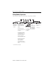
Powermonitor 3000 Master Module Master Module with Communication Options Removable Status Input Connector Terminal Blocks Status Indicators Display Module Port RS-485 (Native) Communication Port NAP Port Powermonitor 3000 Powermonitor 3000 Powermonitor wermonitor 3000 Powermonitor 3000 Powermonitor 3000 ControlNet Channel A Optional RS-232 Port Optional Remote I/O Port Optional DeviceNet Port Publication 1404-IN007F-EN-P - November 2009 Optional Ethernet 10BaseT Port ControlNet Channel B
Powermonitor 3000 Master Module 9 Powermonitor 3000 Display Module The display module is an optional user-interface device. The display module provides the most economical and simplest method for setting up and configuring the master module for operation. The display module has a highly visible, two-line LED display and four operator buttons with tactile feedback. Use the buttons and display to navigate through a series of menus for configuration, commands, and data display.
Powermonitor 3000 Master Module Catalog Number Explanation The Powermonitor 3000 unit has the following catalog number possibilities. 1404 - M4 Bulletin Number 1404 = Power Monitoring and Management Products 05 Type of Device Current Inputs M4 = Master Module with 05 = 5 A three-phase metering, Power Supply setpoints, I/O, and data logging. A= M5 = M4 functionality, firmware upgradeable to an M6 or M8.
Powermonitor 3000 Master Module 11 Quick Start Guidelines The Powermonitor 3000 unit may be used in many electric power monitoring and control systems. Whether your power monitor is a complete power and energy monitor or a component in a plant- or enterprise-wide energy management system, there are a few basic steps to follow to make your unit operational. 1. Install your Powermonitor 3000 master module within a suitable enclosure. Refer to Install the Powermonitor 3000 Unit on page 12. 2.
Powermonitor 3000 Master Module Install the Powermonitor 3000 Unit Only qualified personnel should install, wire, service, and maintain this equipment. Refer to and follow the safety guidelines and pay attention to all warnings and notices in these instructions. ATTENTION Electrostatic discharge can damage integrated circuits or semiconductors. Follow these guidelines when you handle the module: • Touch a grounded object to discharge static potential. • Wear an approved wrist strap grounding device.
Powermonitor 3000 Master Module 13 Mount the master module so that the metal grounding clips on the bottom of the mounting feet make direct contact with the enclosure mounting panel. If the mounting panel is painted, scrape or sand the paint down to bare metal. Use star washers to assure good long-term electrical contact with the mounting panel. Be sure that the mounting panel is properly connected to a low-impedance earth ground.
Powermonitor 3000 Master Module Product Dimensions Use the dimensions in these drawings when mounting the master module. Master Module Dimensions All dimensions are in mm (in.). 14.66 (0.577) 114.30 (4.50) 85.0 (3.346) Mounting 10.43 (0.411) 4.57 (0.180) 4 Places 5.35 (0.211) Powermonitor 3000 125.0 (4.921) Mounting 135.15 (5.321) 114.30 (4.50) 163.17 (6.424) Used Without Display Module 184.15 (7.250) Used With Display Module 5.60 (0.22) Publication 1404-IN007F-EN-P - November 2009 203.
Powermonitor 3000 Master Module 15 Master Module Spacing All dimensions are in mm (in.). 215.9 (8.50) 50.8 (2.00) Minimum Powermonitor 3000 Powermonitor 3000 215.9 (8.50) 101.6 (4.00) Powermonitor 3000 Powermonitor 3000 50.8 (2.00) Minimum 50.8 (2.00) 101.6 (4.00) 50.8 (2.00) General Notes: • Recommended spacing provides reasonable wiring clearance and ventilation. • Maintain approximately 102 mm (4.00 in.) clearance between master modules and other electrical equipment.
Powermonitor 3000 Master Module System Accuracy Considerations User-supplied potential transformers (PTs) and current transformers (CTs), as well as wiring from the CTs to the power monitor, may reduce the accuracy of your power monitor system. The quality of the power monitor’s measurements can be no better than the quality of the signals presented to its input terminals. It is your responsibility to select transformers that are adequate for the desired metering accuracy. ANSI/IEEE C57.
Powermonitor 3000 Master Module 17 Phase Error Phase shift between the primary to secondary signals is another source of inaccuracy introduced by the user-supplied PTs and CTs. Phase shift is generally not of concern for simple voltage or current measurements. When these signals are combined, for instance when calculating line to line voltage or phase power, the effect of phase shift can become significant. The difference in phase error among different transformers causes measurement errors.
Powermonitor 3000 Master Module Wiring and Connecting the Power Monitor ATTENTION Only qualified personnel, following accepted safety procedures, should install, wire, and service the power monitor and its associated components. Before beginning any work, disconnect all sources of power and verify that they are de-energized and locked out. Failure to follow these instructions may result in personal injury or death, property damage, or economic loss.
Powermonitor 3000 Master Module 19 Wiring the Master Module Observe all wire lug sizes and screw torques for terminal blocks wire sizes and screw torques. Refer to Specifications on page 56. Voltage and Current Inputs The following sections give information on the selection of PTs and CTs. Voltage Input and PT Selection The power monitor is designed to connect directly to a power system rated up to 600V line-to-line (347V line-to-neutral). Higher system voltages require the use of user-supplied PTs.
Powermonitor 3000 Master Module The shorting terminal block should be located adjacent to the Powermonitor 3000 master module so that it is readily accessible should service be needed. Use 2.5 mm2 (14 AWG) wire for the short run between the power monitor and the shorting terminal block. Use wiring of 4 mm2 (12 AWG) or larger between the shorting terminal block and the CT so that the additional load of the wiring does not overload the CT and reduce its accuracy.
Powermonitor 3000 Master Module 21 Wiring Diagrams Single-phase Direct Connection Wiring Diagram (Systems < 600V Nominal L-L) Voltage Mode = Single Phase Line L1 L2 N Fuse Fuse Powermonitor 3000 Master Module Customer-supplied CT Shorting Switch or Test Block R14 R11 R12 N/C I1I2I3I4- Y Z N/C V1 I1+ V2 I2+ V3 I3+ N I4+ R14 R11 R12 Y Load L1 (+) L2 (-) GRD K K Z Customer Chassis Ground Publication 1404-IN007F-EN-P - November 2009
Powermonitor 3000 Master Module Single-phase with PTs Wiring Diagram Line L1 L2 Voltage Mode = Single Phase N Fuse Fuse Customer-supplied CT Shorting Switch or Test Block R14 R11 R12 N/C I1I2I3I4- Y Customer Chassis Ground Publication 1404-IN007F-EN-P - November 2009 L1 (+) L2 (-) GRD K Z N/C V1 I1+ V2 I2+ V3 I3+ N I4+ R14 R11 R12 Load Powermonitor 3000 Master Module Y K Z
Powermonitor 3000 Master Module 23 Three-phase Four-wire Wye Direct Connect Wiring Diagram (Systems < 600V Nominal L-L) Line L1 L2 Voltage Mode = Wye L3 N Fuse Fuse Fuse Customer-supplied CT Shorting Switch or Test Block R14 R11 R12 N/C I1I2I3I4R14 R11 Load Powermonitor 3000 Master Module Y L1 (+) L2 (-) GRD K Z N/C V1 I1+ V2 I2+ V3 I3+ N I4+ R12 Y K Z Customer Chassis Ground Publication 1404-IN007F-EN-P - November 2009
Powermonitor 3000 Master Module Three-phase Four-wire with PT’s Wiring Diagram Line L1 L2 L3 Voltage Mode = Wye N Fuse Fuse Fuse Customer-supplied CT Shorting Switch or Test Block R14 R11 R12 N/C I1I2I3I4- Y Customer Chassis Ground Publication 1404-IN007F-EN-P - November 2009 L1 (+) L2 (-) GRD K Z N/C V1 I1+ V2 I2+ V3 I3+ N I4+ R14 R11 R12 Load Powermonitor 3000 Master Module Y K Z
Powermonitor 3000 Master Module 25 Three-phase Three-wire Grounded Wye Direct Connection Wiring Diagram (Systems < 600V Nominal L-L) Line L1 L2 Voltage Mode = Wye L3 Fuse Fuse Fuse Customer-supplied CT Shorting Switch or Test Block R14 R11 R12 N/C I1I2I3I4- Y L1 (+) L2 (-) GRD K Z N/C V1 I1+ V2 I2+ V3 I3+ N I4+ R14 R11 R12 Load Powermonitor 3000 Master Module Y K Z Customer Chassis Ground Publication 1404-IN007F-EN-P - November 2009
Powermonitor 3000 Master Module Three-phase Three-wire Grounded Wye with PTs Wiring Diagram Line L1 L2 Voltage Mode = Wye L3 Fuse Fuse Fuse Customer-supplied CT Shorting Switch or Test Block R14 R11 R12 N/C I1I2I3I4- Y Customer Chassis Ground Publication 1404-IN007F-EN-P - November 2009 L1 (+) L2 (-) GRD K Z N/C V1 I1+ V2 I2+ V3 I3+ N I4+ R14 R11 R12 Load Powermonitor 3000 Master Module Y K Z
Powermonitor 3000 Master Module 27 Three-phase Three-wire Delta with Three PTs and Three CTs Wiring Diagram Line Voltage Mode = Delta 3 CT L1 L2 L3 Fuse Fuse Fuse Customer-supplied CT Shorting Switch or Test Block R14 R11 R12 N/C I1I2I3I4- Y L1 (+) L2 (-) GRD K Z N/C V1 I1+ V2 I2+ V3 I3+ N I4+ R14 R11 R12 Load Powermonitor 3000 Master Module Y K Z Customer Chassis Ground Publication 1404-IN007F-EN-P - November 2009
Powermonitor 3000 Master Module Three-phase Three-wire Delta with Three PTs and Two CTs Wiring Diagram Voltage Mode = Delta 2 CT Line L1 L2 L3 Fuse Fuse Fuse Customer-supplied CT Shorting Switch or Test Block R14 R11 R12 N/C I1I2I3I4- Y Customer Chassis Ground Publication 1404-IN007F-EN-P - November 2009 L1 (+) L2 (-) GRD K Z N/C V1 I1+ V2 I2+ V3 I3+ N I4+ R14 R11 R12 Load Powermonitor 3000 Master Module Y K Z
Powermonitor 3000 Master Module 29 Three-phase Three-wire Open Delta with Two PTs and Three CTs Wiring Diagram Voltage Mode = Open Delta 3 CT Line L1 L2 L3 Fuse Fuse Customer-supplied CT Shorting Switch or Test Block R14 R11 R12 N/C I1I2I3I4- Y L1 (+) L2 (-) GRD K Z N/C V1 I1+ V2 I2+ V3 I3+ N I4+ R14 R11 R12 Load Powermonitor 3000 Master Module Y K Z Customer Chassis Ground Publication 1404-IN007F-EN-P - November 2009
Powermonitor 3000 Master Module Three-phase Three-wire Open Delta with Two PTs and Two CTs Wiring Diagram Voltage Mode = Open Delta 2 CT Line L1 L2 L3 Fuse Fuse Customer-supplied CT Shorting Switch or Test Block R14 R11 R12 N/C I1I2I3I4- Y Customer Chassis Ground Publication 1404-IN007F-EN-P - November 2009 L1 (+) L2 (-) GRD K Z N/C V1 I1+ V2 I2+ V3 I3+ N I4+ R14 R11 R12 Load Powermonitor 3000 Master Module Y K Z
Powermonitor 3000 Master Module 31 Three-phase Three-wire Grounded L2(B) Phase Open Delta Direct Connect with Three CTs Wiring Diagram (Systems < 600V Nominal L-L) Voltage Mode = Open Delta 3 CT Line L1 L3 Distribution Ground Fuse Fuse Voltage must not exceed 347V L-L (otherwise, step down transformers are required).
Powermonitor 3000 Master Module Three-phase Three-wire Delta Direct Connect with Three CTs Wiring Diagram (Systems < 600V Nominal L-L) Voltage Mode = Direct Delta 3 CT Line L1 L2 L3 Fuse Fuse Fuse Customer-supplied CT Shorting Switch or Test Block R14 R11 R12 N/C I1I2I3I4- Y Load Publication 1404-IN007F-EN-P - November 2009 L1 (+) L2 (-) GRD K Z N/C V1 I1+ V2 I2+ V3 I3+ N I4+ R14 R11 R12 Customer Chassis Ground Powermonitor 3000 Master Module Y K Z
Powermonitor 3000 Master Module 33 Three-phase Three-wire Delta Direct Connect with Two CTs Wiring Diagram (Systems < 600V Nominal L-L) Line L1 L2 Voltage Mode = Direct Delta 2 CT L3 Fuse Fuse Fuse Customer-supplied CT Shorting Switch or Test Block R14 R11 R12 N/C I1I2I3I4- Y L1 (+) L2 (-) GRD K Z N/C V1 I1+ V2 I2+ V3 I3+ N I4+ R14 R11 R12 Load Powermonitor 3000 Master Module Y K Z Customer Chassis Ground Publication 1404-IN007F-EN-P - November 2009
Powermonitor 3000 Master Module Control Power The power monitor draws a nominal 15VA control power. Catalog numbers 1404-MxxxA-xxx require nominal control power of 120…240V AC or 125…250V DC. The power supply is self-scaling. Catalog numbers 1404-MxxxB-xxx require nominal control power of 24V DC.
Powermonitor 3000 Master Module 35 All Status Inputs are common to an internal 24V DC source on the SCOM terminal. Status input terminals S1 and S2 are positive polarity and SCOM is negative polarity. For optimal EMC performance, we recommend wiring the status inputs by using shielded cable, Belden 8771 or equivalent, with the cable shield grounded at both ends where possible. Status Input Connections N.O.
Powermonitor 3000 Master Module The KYZ output is a solid-state relay designed for low-current switching and long life. Its normal application is to provide a pulse based on energy usage (or one of five other parameters) to an external pulse accumulator. Terminal K is common, Y is normally-open, and Z is normally-closed. Refer to the Powermonitor 3000 Unit User Manual, publication 1404-UM001, for further information on the application and operation of relay and KYZ outputs.
Powermonitor 3000 Master Module 37 Native RS-485 Communication Wiring The RS-485 communication standard supports multi-drop communication among as many as 32 stations or nodes. The RS-485 port is also used for master module firmware upgrades in the field. RS-485 communication wiring should be installed in a daisy-chain configuration. We recommend that you use Belden 9841 two-conductor shielded cable or equivalent. The maximum cable length is 1219 m (4000 ft).
Powermonitor 3000 Master Module RS-485 Connections IBM Compatible Personal Computer Shield Connection (See Note 4) External RS-232C to RS-485 Converter (See Note 3) SHLD A B 150 Ω Terminating Resistor (See Note 2) Or PLC Processor Powermonitor 3000 Device #1 SHLD Or SLC Processor RS-485 _ + Powermonitor 3000 Device #2 Or ControlLogix Processor SHLD RS-485 _ + Notes: 1) Three-device network shown. Up to 31 DF1 Slave Devices can be connected to a DF1 Master without the use of a repeater.
Powermonitor 3000 Master Module 39 Optional RS-232 Communication Powermonitor 3000 units with a catalog number ending in -232 are equipped with an RS-232 serial communication port in addition to the native RS-485 port. The RS-232 communication standard supports point-to-point communication among two stations or nodes. You must select either optional RS-232 communication or native RS-485 communication. The two ports do not operate at the same time.
Powermonitor 3000 Master Module Optional Remote I/O Communication Powermonitor 3000 units with a catalog number ending in -RIO are equipped with a remote I/O port in addition to the native RS-485 port. Allen-Bradley remote I/O is a robust, widely used industrial data network that uses twinaxial cable as its physical media. The power monitor emulates a logical quarter rack and supports both polled I/O and block transfer communication.
Powermonitor 3000 Master Module 41 Configuration options for optional remote I/O communication include the logical rack address and module group (the power monitor is always one-quarter rack), and data rate. Defaults are rack 1, group 0, 57.6 Kbps. Refer to the Powermonitor 3000 Unit User Manual, publication 1404-UM001. Refer to the note at the beginning of Communication Wiring on page 36.
Powermonitor 3000 Master Module Optional DeviceNet Communication Powermonitor 3000 units with a catalog number ending in -DNT are equipped with a DeviceNet port in addition to the native RS-485 port. The DeviceNet network is an open-standard, multi-vendor, industrial device data network that uses a variety of physical media. The DeviceNet network also provides 24V DC power to devices connected to the network.
Powermonitor 3000 Master Module 43 Connecting Powermonitor 3000 to Other DeviceNet Devices VPowermonitor 3000 Device CAN_L SHLD CAN_H 121 Ω Terminating Resistor (See Note 2) V+ IBM Compatible Personal Computer With 1784 PCDPCMCIA Interface Card Or 1770-KFD Interface Box VCAN_L SHLD CAN_H Or PLC With 1771-SDN Scanner V+ Notes: 1) Example network protrayed.
Powermonitor 3000 Master Module Ethernet Wiring Connections Terminal Signal Function 1 TX+ TX+ 2 TX- TX- 3 RX+ RX+ RX- RX- 4 5 6 7 8 Powermonitor 3000 Ethernet Network Example Ethernet Switch LAN SLC 500 Controller Powermonitor 3000 Master Module #1 Personal Computer with RSLinx and RSPower 32 or RSEnergyMetrix Software PLC-5 Controller Powermonitor 3000 Master Module #2 ControlLogix Controller Publication 1404-IN007F-EN-P - November 2009
Powermonitor 3000 Master Module 45 Refer to the note at the beginning of Communication Wiring on page 36. Configuration options for optional Ethernet communication include the IP (Internet Protocol) address, subnet mask, default gateway IP address, and protocol. Defaults are: • IP address: 192.168.254.xxx where xxx is the Device ID assigned at the factory in the range 1…247. • subnet mask: 255.255.0.0. • default gateway IP address: 128.1.1.1. • protocol: CSP (PCCC) and CIP (EtherNet/IP network).
Powermonitor 3000 Master Module Refer to the following documentation for ControlNet network wiring requirements and general ControlNet information: • ControlNet Coax Media Planning and Installation Guide, publication CNET-IN002 • ControlNet Coax Tap Installation Instructions, publication 1786-IN007 Connecting a Programming Terminal to the Network by Using a 1786-CP Cable To connect a programming terminal to the network using a 1786-CP cable, you have the following options: • Using a 1784-KTC, 1784-KTC
Powermonitor 3000 Master Module 47 The 1786-CP cable can be plugged into any ControlNet product’s NAP to provide programming capability on the ControlNet network. A programming terminal connected through this cable is counted as a node and must have a unique network address. ATTENTION Use a 1786-CP cable when connecting a programming terminal to the network through NAPs. Using a commercially available RJ-style cable could result in network failure.
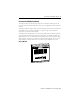
Powermonitor 3000 Master Module Powermonitor 3000 Status Indicators Powermonitor 3000 MODULE STATUS RX RS-485 TX All Powermonitor 3000 Models Status Indicators Indicator Status Description Module Status Off Control power is off or insufficient. Steady red Major fault; internal self-test has failed. If a power cycle does not correct the problem, call customer support. Steady green Power monitor is operating normally. Off The RS-485 bus is idle; no active data is present.
Powermonitor 3000 Master Module 49 RS-232 Status Indicators Powermonitor 3000 F1 RX TX } RS-232 RS-232 Optional Communication (catalog numbers ending in -232) Indicator Status Description F1 Off Not used. RS-232 RX Off The RS-232 bus is idle; no active data is present. Flashing green Power monitor is receiving data. RS-232 TX Off The power monitor is not transmitting any data onto the RS-232 bus. Flashing green The power monitor is transmitting data.
Powermonitor 3000 Master Module DeviceNet Status Indicators Powermonitor 3000 F1 F2 NETWORK STATUS DeviceNet Optional Communication (catalog numbers ending in -DNT) Indicator Status Description F1 Off Not used. F2 Off Not used. Network Status Off Power is off or the power monitor is not online. Flashing green Network status is OK, no connections established. Steady green Network status is OK, connections established. Flashing red Recoverable communication failure; port is restarting.
Powermonitor 3000 Master Module 51 EtherNet/IP Optional Communication (catalog numbers ending in -ENT) Indicator Status Description F2 Off Not used. Network Status Off No power. Flashing green No established connections. Steady green Connected; has at least one established connection. Flashing red Connection timeout; one or more connections to this device has timed-out. Steady red Duplicate IP; the IP address assigned to this device is already in use.
Powermonitor 3000 Master Module Access Self-test and Diagnostic Data You can access valuable diagnostic information by using the optional display module. 1. Connect the display module to the master module by using the display module cable. 2. Using the four control keys, navigate through the menus to Display - Status and press Enter. The display module then displays the following data. Use the up and down arrow keys to step through the status data.
Powermonitor 3000 Master Module 53 Display Module Status Display Description DMSTA Displays the display-module status bitfield as a hex number. A non-zero value may indicate an anomaly, although a non-zero value may appear if a display module is connected to an operating master module. DM FRN Indicates the display-module firmware revision. MM/DD/YYYY Displays the current date. HH/MM/SS Displays the current time. RELAY Shows the status of the Form 4C relay.
Powermonitor 3000 Master Module Cleaning Instructions ATTENTION Electrostatic discharge can damage integrated circuits or semiconductors. Follow these guidelines when you handle the module: • Touch a grounded object to discharge static potential. • Wear an approved wrist strap grounding device. • Do not open the module or attempt to service internal components. • Use a static safe work station, if available. • Keep the module in its static shield bag when not in use.
Powermonitor 3000 Master Module 55 Field Service Considerations If the power monitor requires servicing, contact your nearest Rockwell Automation sales office. To minimize your inconvenience, the initial installation should be performed in a manner that makes removal easy. • A CT shorting block should be provided to allow the Powermonitor 3000 master-module current inputs to be disconnected without making the user-supplied CTs an open circuit.
Powermonitor 3000 Master Module Specifications Measurement Accuracy and Range Powermonitor 3000 Master Module - 1404-M4, 1404-M5, 1404-M6, 1404-M8 Parameter Accuracy in % of Full Scale at 25 °C (77 °F) 50/60 Hz Unity Power Facator Nominal/Range 1404-M4 1404-M5 1404-M6 1404-M8 Voltage sense inputs: V1, V2, V3 ±0.2% ±0.05% ±0.05% ±0.05% 347V/15…399V L-N rms 600V/26…691V L-L rms Current sense input: I1, I2, I3, I4 ±0.2% ±0.05% ±0.05% ±0.05% 5 A/50 mA…10.6 A rms Frequency ±0.05 Hz ±0.
Powermonitor 3000 Master Module 57 Input and Output Ratings Attribute Value Current sense inputs: I1, I2, I3, I4 Overload withstand: 15 A continuous, 200 A for 1 s Burden: 0.05VA Impedance: 0.002 Ω Max crest factor at 5 A: 3 Starting current: 5 mA Status inputs Contact closure (internal 24V DC) Control relay KYZ output (1) ANSI C37.
Powermonitor 3000 Master Module Technical Specifications - 1404-M4, 1404-M5, 1404-M6, 1404-M8 Attribute Dielectric withstand Terminal blocks 1404-M4, 1404-M5, 1404-M6, 1404-M8 Control power 2000V Voltage inputs 2000V Current inputs 2000V Status inputs 500V Control relays 1600V Power supply and voltage input terminals 4 mm2 (12 AWG) max, 1.02 N•m (9 lb•in) torque, 75 °C (167 °F) or higher copper wire only Relay, KYZ outputs, current input 2.5 mm2 (14 AWG) max, 1.18 N•m (10.
Powermonitor 3000 Master Module 59 Product Approvals Powermonitor 3000 units have the following approvals and certifications. EtherNet/IP Conformance Testing All products equipped with an EtherNet/IP communication port bear the mark shown below. This mark indicates the power monitor has been tested at an Open Device Vendor Association (ODVA) independent test lab and has passed the EtherNet/IP conformance test.
Powermonitor 3000 Master Module CE Certification If this product bears the CE marking, it is approved for installation within the European Union and EEA regions. It has been designed to meet the following directives.
Powermonitor 3000 Master Module 61 Additional Resources Refer to these power and energy management documents for more information. . For this information Refer to Publication Powermonitor 3000 User Manual, publication 1404-UM001 Provides details about configuring and using the master module. Powermonitor 3000 Display Module Installation Instructions, publication 1404-IN005 Provides details about how to mount and wire the display module. Bulletin 1403 Powermonitor II Tutorial, publication 1403-1.0.
Powermonitor 3000 Master Module Notes: Publication 1404-IN007F-EN-P - November 2009
Powermonitor 3000 Master Module 63 Notes: Publication 1404-IN007F-EN-P - November 2009
Rockwell Automation Support Rockwell Automation provides technical information on the Web to assist you in using its products. At http://www.rockwellautomation.com/support/, you can find technical manuals, a knowledge base of FAQs, technical and application notes, sample code and links to software service packs, and a MySupport feature that you can customize to make the best use of these tools.