
Specifications


MCD3000 Series
38 MG.15.A4.22 - VLT is a registered Danfoss trademark
Desi
g
n Guide
Application Typical
Start Current
General & Water
Agitator 4.0 x FLC
Centrifugal Pump 3.5 x FLC
Compressor (Screw, unloaded) 3.0 x FLC
Compressor (Reciprocating, unloaded) 4.0 x FLC
Conveyor 4.0 x FLC
Fan (damped) 3.5 x FLC
Fan (undamped) 4.5 x FLC
Mixer 4.5 x FLC
Positive Displacement Pump 4.0 x FLC
Submersible Pump 3.0 x FLC
Metals & Mining
Belt Conveyor 4.5 x FLC
Dust Collector 3.5 x FLC
Grinder 3.0 x FLC
Hammer Mill 4.5 x FLC
Rock Crusher 4.0 x FLC
Roller Conveyor 3.5 x FLC
Roller Mill 4.5 x FLC
Tumbler 4.0 x FLC
Wire Draw Machine 5.0 x FLC
Food Processing
Bottle Washer 3.0 x FLC
Centrifuge 4.0 x FLC
Dryer 4.5 x FLC
Mill 4.5 x FLC
Palletiser 4.5 x FLC
Separator 4.5 x FLC
Slicer 3.0 x FLC
Pulp and Paper
Dryer 4.5 x FLC
Re-pulper 4.5 x FLC
Shredder 4.5 x FLC
Petrochemical
Ball Mill 4.5 x FLC
Centrifuge 4.0 x FLC
Extruder 5.0 x FLC
Screw Conveyor 4.0 x FLC
Transport & Machine Tool
Ball Mill 4.5 x FLC
Grinder 3.5 x FLC
Material Conveyor 4.0 x FLC
Palletiser 4.5 x FLC
Press 3.5 x FLC
Roller Mill 4.5 x FLC
Rotary Table 4.0 x FLC
Lumber & Wood products
Bandsaw 4.5 x FLC
Chipper 4.5 x FLC
Circular Saw 3.5 x FLC
Debarker 3.5 x FLC
Edger 3.5 x FLC
Hydraulic Power Pack 3.5 x FLC
Planer 3.5 x FLC
Sander 4.0 x FLC
ATTENTION
The above start current requirements are
typical and appropriate in most circumstances.
However, start torque requirements and performance
of motors and machines does vary. For greater
accuracy use the advanced model selection
procedure.
ATTENTION
For applications that operate outside the
standard MCD3000 ratings of 10 starts per
hour, 50% duty cycle, 40
o
C, <1000 metres consult
your local supplier.
%HZERGIHQSHIPWIPIGXMSRTVSGIHYVI
This method uses data on the motor and load to
determine the required start current and assumes
operation within the standard MCD3000 ratings of 10
starts per hour, 50% duty cycle, 40
o
C, <1000 metres.
Advanced model selection should be used where
typical figures listed in the standard model selection
procedure are not considered certain enough.
Advanced model selection is also recommended for
high inertia applications and installations involving large
motors where motor start performance can vary
widely.
1. Calculate the required starting torque as a
percentage of motor Full Load Torque (FLT).
Generally machine suppliers will be able to provide
data regarding the start torque requirements of
their machinery. Where this data is not provided
as a percentage of motor FLT it will need to be
converted.
A motor’s full load torque can be calculated as
follows
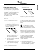
2. Calculate the minimum start current required by
the motor to produce the required torque as
calculated above.
I
ST
=
LRC x
T
ST
LRT
I
ST
= Minimum required start current
LRC = Motor Locked Rotor Current
LRT = Motor Locked Rotor Torque
T
ST
= Required start torque