
User Manual


PART NUMBER CONFIGURATION
S:
SA
P(Force)
-
(Window width)
-
(options)
-
(options)
MP= Manual Press
SAP= Semi-Automatic Press
AP= Automatic Press
CUSTOMER SATISFACTION…………“Whatever it takes”
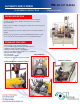
AUTOMATIC SERVO PRESS
CHART NOTES:
Features for 20" window AP12-20 AP32-20 AP55-20 AP80-20 AP110-20
Force KN / Tons 12 / 1.3 32 / 3.6 55 / 6.2 80 / 9 110 / 12.3
Footprint (W" x D” x H") (in) 28x25.5x78 28x25.5x82 28x25.5x84 28x25.5x86 28x25.5x92
Ram Stroke (in) 5.5 5.5 5.5 5.5 5.5
Vertical tooling / Product Area (in) 11.5 11.5 11.5 11.5 11.5
Ram Approach Speed (in/sec) 3 3 3 3 3
Ram Press Speed- Programmable .1-3 in/sec .1-3 in/sec .1-3 in/sec .1-3 in/sec .1-3 in/sec
Drive Type Screw Screw Screw Screw Screw
Accuracy (in) 0.0002 0.0002 0.0002 0.0002 0.0002
Repeatability (in) 0.0001 0.0001 0.0001 0.0001 0.0001
Tooling surface on Ram (W" x D") 6.5x4 9 x 5 9 x 5 10 x 6 10 x 6
Max Product width accepted (in) * 20 20 20 20 20
Throat Depth (behind Ram) (in) 14.5 14.5 14.5 14.5 14.5
Machine Front to Press center (in) 10.5 10.5 10.5 10.5 10.5
Force, Speed, SPC Graphing std std std std std
Safety Light Curtains std std std std std
SOFTWARE
1) Ram strokes available up to 20 inches
2) Higher Ram Approach speeds Available
3) Tooling Surface should be centered ( 80% of Load ) on
ram
4) Deeper throat depths available
* 24” and 36” Product windows optional
(TS)
Top & Bottom Press Tooling Set
(TSET) Top & Bottom Tooling set w/ Electrical Pin Check
(PTF) Press-Thru fixture
(HC) Hand crank (x-axis) Top Tooling Position
(PTT) Programmable Position Top Tooling (x-axis)
(FS) Bar Code Scanning - Fixed Location - (2D)
(HS) Hand Held Bar Code Scanner
(MPxx-24) 24" Product Window
(MPxx-36) 36" Product Window
(LT) Light Tower w/ alarm
(TF) Tray Feeders
(RA) Robotic Assist Loading
SPECIAL NOTES: