
User's Manual
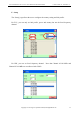

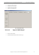

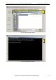
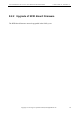
Table Of Contents
- Version 1.0
- 3.1 Product Package
- 3.1.1 Basic Package Content
- 3.1.2 Product Specifications
- 4 Hardware Installation
- 5 Software Installation
- 5.1 Software Content of Shipment Package
- 5.2 PC Side Prerequisites
- 5.3 PC Side Libraries and API Document
- 5.4 Default Ex-Factory IP Settings
- 5.5 Changing IP Addresses
- 5.5.1 "Netfinder" Program Method
- 5.5.1.1 Hardware Setup
- 5.5.1.2 Software Setup
- 5.5.1.3 Search CS203 Board
- 5.5.1.4 Assign CS203 IP, Server IP and TCP Timeout
- 5.5.2 "CS203 GPIO" Program Method
- 5.6 Status Verification
- 5.7 Exception Situations
- 5.8 Finding a "Lost" CS203
- 6 Demo Applications
- 7 Middleware Connectivity
- 8 Software Upgrade
- 9 Regulatory Information
- Appendix A. RFID Basics
- Appendix B. Operation Profiles
- Appendix C. RF channels
- Appendix D. FAQ
- Appendix E. Common Mistakes
- Appendix D. Technical Support

CSL CS203ETHER-2 EPC CLASS 1 GEN 2 RFID INTEGRATED READER USER'S MANUAL, VERSION 1.0
Copyright © Convergence Systems Limited, All Rights Reserved
60
Appendix A. RFID Basics
Passive tag RFID technology involves the reader, the antenna and the tag.
The reader sends out energy in the relevant frequency band to the antenna via RF cables, and
the antenna radiates the energy out. This energy impinges on an RFID tag.
The RFID tag consists of an antenna coupled to an RFID IC. This IC converts the AC voltage
it receives at the antenna port to DC voltage that in turn is used to empower the digital circuit
inside.
The digital circuit then turns on and off some components connected to the antenna port,
thereby changing its scattering behavior, in a pre-designed clock rate.
This changing of antenna port parameters then causes a “modulation” of the back-scattered RF
energy.
This modulated back-scattered energy is detected by the reader and the modulation is captured
and analyzed.