SPX-7500 Series Operations Manual Suprex® Reader Extender - RS-485 Interface SPX-7500_MAN_082112
Cypress Suprex SPX-7500 Series SPX-7500 Series: This manual covers the operation and setup of the Cypress Suprex RS-485 based SPX-7500 series units. Features: -- Supports 1 reader and associated I/O. -- Expandable to 8 total readers and associated i/O with EXP-2000 modules -- Service mode for setup and configuration of Expansion modules.
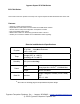
External Reader / Panel connections and DIP Switch Settings 1 - 8 to 16 VDC In 2 - Ground RS-485 Interface SPX-7500 Central Status LED 1- Relay 4 N.O. 2- Relay 4 Com 3 - Relay 4 N.C. 4 - Relay 3 N.O. 5 - Relay 3 Com 6 - Relay 3 N.C. 7 - Ground 8 - Aux out 9 - R2 in 10 - R1 in 1 - exp (+) 2 - exp (-) 3 - +5 VDC out 4 - Prog Res 4 5 - Prog Res 3 6 - LED In 7 - D1/Data out 8 - D0/Clk out 1 - 8 to 16 VDC In 2 - Ground RS-485 Interface SPX-7500 Remote Status LED 1- Relay 2 N.O.
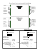
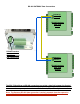
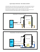
Quick Reference For Typical Connections SPX-7500 Series Central DC Power Supply +8 to +16 VDC Ground Diagnostic LED Access Control Panel R1 Input Controls Strike on Remote LED In D1/Data Out D0/Clock Out R1 IN See page 10 for other strike control options SPX-7500 Series Remote DC Power Supply +8 to +16 VDC Ground Diagnostic LED R1 N.O. R1 Com R1 N.C.
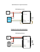
RS-485 GATEWAY Data Connections RS-485 (+) RS-485 (-) RS-485 Interface SPX-7500 Central RS-485 Interface to connect SPX-7500 remote and central units RS-485 (+) RS-485 (-) RS-485 Interface SPX-7500 Remote The SPX-7500 utilizes an RS-485 connection to provide a data link between the Central and Remote RFX units. This RS-485 connection provides a data connection in the same manner as other suprex products that use IP Newtwork, RF, or Fiber-Optic connections.
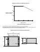
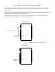
Temperature Rating vs Voltage Derating Curve 80 55 Ambient Temperature (Degrees Celsius) 35 -40 8 10 12 14 16 Supply Voltage Temperature/Voltage de-rating curve The Suprex units should be operated with a filtered 12 Volt nominal DC supply. Any voltage between 8 and 16 volts can be utilized by following the temperature /voltage derating curve. Voltage should not exceed 16 VDC under normal operating conditions. Cypress Suprex® SPX-7500 Enclosure Dimensions 4.45 3.15 0.80 2.00 3.08 ø0.20 X 4 0.
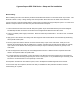
Cypress Suprex SPX-7500 Series - Setup and Pre-installation Bench Testing: Before installing the units in the field they should be assembled and tested at a convenient “Bench top” location. This will make it easier to verify / change settings and check operation when both units are visible at the same time. It is also a chance to become familiar with the system if this is the first time using the Suprex system. It is much more difficult to setup and test the units when they are several thousand feet apart.
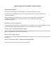
Cypress Suprex SPX-7500 Series - Status Indicators LED Diagnostic Indicator: The LED Diagnostic indicator provides information on the operational status of the unit. If the units are not communicating, viewing the diagnostic indicator LED’s may help to determine the nature of the problem. When the Suprex units are operating correctly and have a valid communication channel between the Remote and Central units, the Diagnostic indicators on each unit will flash green rapidly (2-3 flashed per second).
Cypress Suprex 7500 Series - Door Strike and LED I/O To activate the relay on the Remote unit, connect as shown below. These connections can be used to allow the Remote relay to operate a DOOR STRIKE, GATE, or other locking hardware. Refer to following pages in this document for details of each I/O operation and connection. There are two relays available for accessory outputs at the Remote end. Either relay can be used to provide the Door Strike or Gate activation function. This example uses Relay 1.
Cypress Suprex 7500 Series - Door Strike and LED I/O The Cypress SPX-7500 provides additional data channels to support access control hardware such as door strikes, tamper alarms, request to exit status, etc. These signals are sent to and from the Remote and Central units without the need to run additional wiring. The accessory control I/O use active low inputs. When the inputs are floating (nothing connected) the associated output will be set to a high level.
Cypress Suprex Series - Relay Controls Suprex® Central Suprex® Central Relay 2 IN Input Signal Relay 1 IN Input Signal Red arrow denotes direction of command signal Relay 2 N.O. Relay 2 Com Relay 2 N.C. Suprex® Remote Contact Outputs Relay 1 N.O. Relay 1 Com Relay 1 N.C.
Cypress Suprex Series - Relay Controls Relay 4 N.O. Relay 4 Com Relay 4 N.C. Suprex® Central Relay 3 N.O. Relay 3 Com Relay 3 N.C. Suprex® Central Contact Outputs Contact Outputs Red arrow denotes direction of command signal Suprex® Remote Suprex® Remote Relay 4 IN Relay 3 IN Input Signal (5Volts DC Maximum) Input Signal (5Volts DC Maximum) Relay 3 functions as an Alarm relay and monitors the condition of the communication link between the Central and Remote units.
SPX-XXXX Application Note Using Supervised Contacts with the SPX-series Extenders Applies to the following products: SPX-5501, SPX-5601, SPX-5521, SPX-5621, SPX-7400, SPX-7410, SPX-7200, SPX-7500, All RIM series products. This application note describes the connections necessary to convey supervised contact status over a Suprex® communication link. The configurations described in this app note should apply to most panels that utilize supervised contacts.
SPX-7500 Setup - Using Expansion Modules Before using EXP-2000 Expansion modules with the SPX-7500 system, it will be necessary to perform a short configuration process. This process determines if the 7500 will utilize expansion modules, and if so, how many will be used with the system. Each SPX-7500 link can support up to 8 expansion modules. SPX-7500 units are shipped in the factory default condition. Factory default units will be setup to function as SPX-7500 units without expansion modules.
Cypress Suprex Series - Wiegand Expansion Module Panel “Central” interface R1 IN R1 Input Controls Strike on Remote D0/Clock Out D1/Data Out LED In Access Control Panel 485(-) 485(+) Ground +8 to +16 VDC DC Power Supply 8 to 16 VDC In Ground 485(+) 485(-) +5 VDC Out Prog Res 4 Prog Res 3 LED Input D1 Output D0 Output * EXP-2000 Central Unit RLY4 N.O. RLY4 Com RLY4 N.C. RLY3 N.O. RLY3 Com RLY3 N.C.
Cypress Suprex Series - Wiegand Expansion Module Reader/Door “Remote” interface D0/Clock In D1/Data In LED Out Door Strike Output R1 N.C. R1 Com R1 N.O. Card Reader 485(-) 485(+) DC Power Supply Ground +8 to +16 VDC 8 to 16 VDC In Ground 485(+) 485(-) +5 VDC Out RLY4 Input (5V) RLY3 Input (5V) LED Output D1 Input D0 Input * EXP-2000 Remote Unit RLY2 N.O. RLY2 Com RLY2 N.C. RLY1 N.O. RLY1 Com RLY1 N.C.